|
Flybarless Collective Rotor head modification II
|
||
|
making the main body
making the cyclic control system
an introduction to electronic components building an airborne video system
|
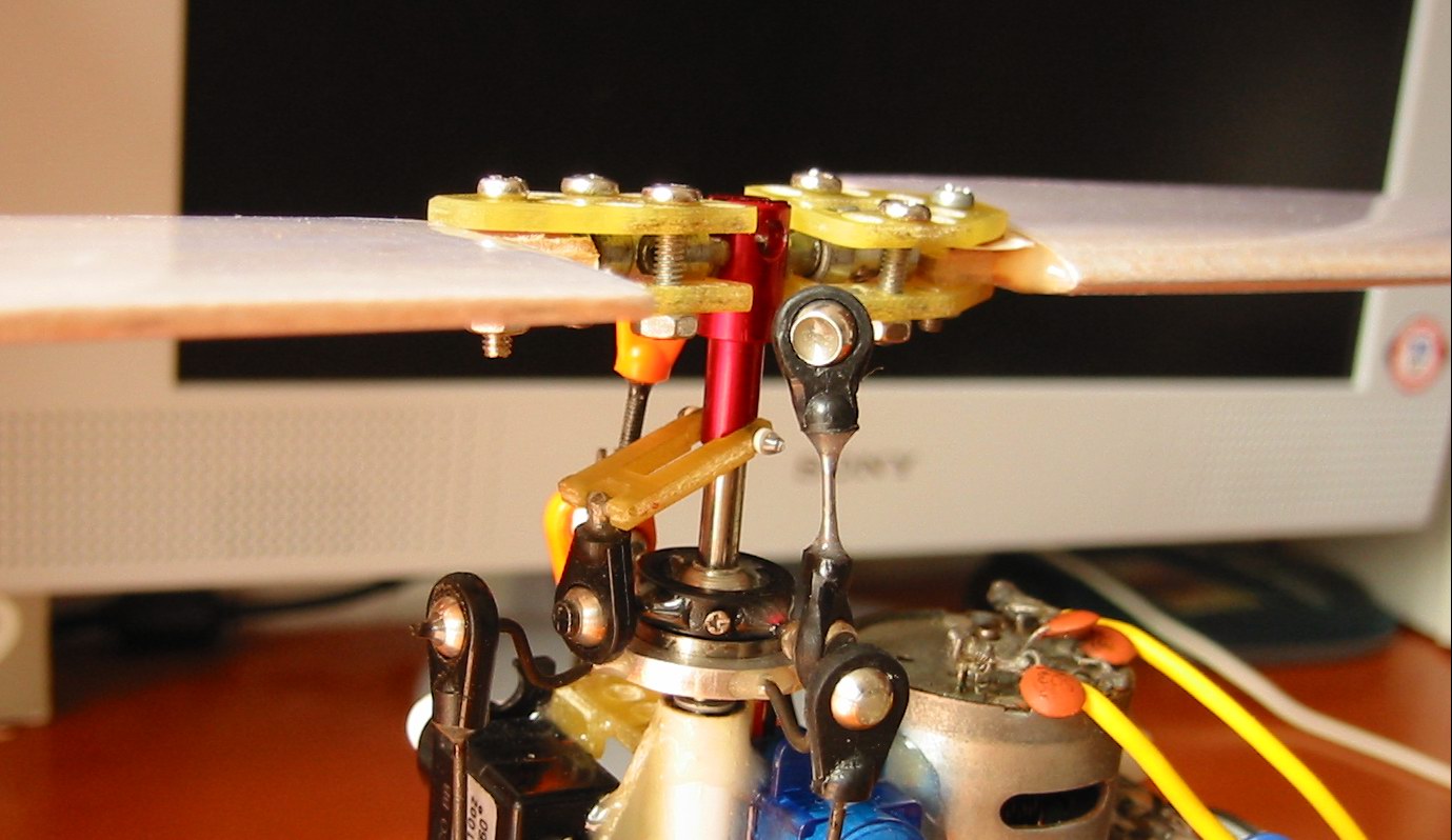
As I know, all the RC helicopter have tester damper in their rotor head. In my fixed pitch design, the performance is still acceptable albeit no tester damper can be found. However, this can't be the same with a flybarless rotor head. In my first flybarless rotor head, the feathering shaft is fixed firmly and the consequence is a really bad respond. the swashplate was even broken as the force acting on it is too large. It was very frustrating that I had to give up that design. Weeks later, I finally find a suitable stuff to redesign my rotor head. Here is my second try:
The importance of tester damper is far outstrip my imagination. without it, the cyclic respond is very robust. The difference is just so obvious when it is introduced to the rotor head. It make the cyclic respond much smooth. It is hard to find the right stuff from the shelf to make the new rotor head. But things change as I find a Kyosho EP part which might be suitable for the job. here is the part list for the new CP rotor head:
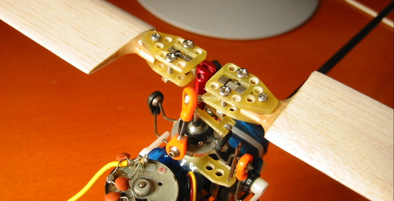
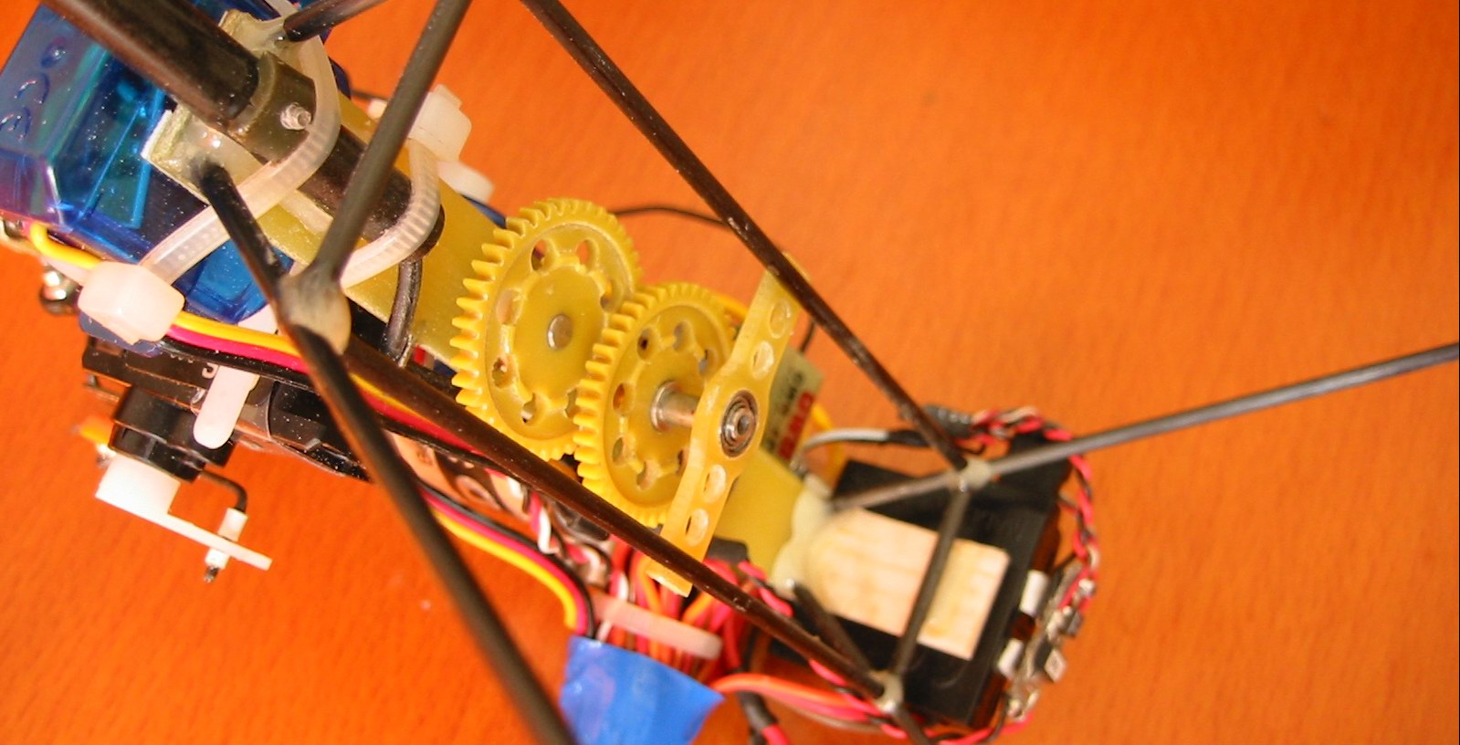
Can you figure out the difference between the new CP rotor head and the original one? If you take a close look at the photo above, you would find that there are some yellow object below the feathering shaft. They come from silicone tube which act as tester damper here. The hand-made symmetrical blades are shorter than the original MS carbon blades. In order to get the same lift, the rotor head much run faster (i.e. higher rpm). The motor needs to be move further apart from the gearwheel as a bigger pinion with higher number of teeth has to be used. I was so unwilling to remove the motor from the main frame as it is stick by epoxy! There is also a modification in the gear reduction unit. Since the force acting on the gearwheel become larger when heavier blades are used, the original one fail to withstand this additional force. here is the changes that had been made:
Here are the blades that I made for the CP head. Lead are added to the blade tip in order to add stability. However, mishap always follow me. The blade roots are not strong enough to support the tip weight (5g) at high rpm and they just broken in a test flight and the helicopter smack into the ground....
I get tired making these wooden blades and want to have a break here. Maybe I'm not a guy to make good blades. Anyway, if you want to donate a pair of sturdy CP blades to me, I would like to continue my work. haha!!
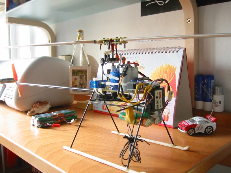
In the end, I started to focus on my CP II design again. The original gearwheels are replaced by one single black gearwheel. Also, the tail rotor had been replaced by a DD GWS power system. this combination provide quicker and more accurate control on the tail.
several videos had been taken and placed at the video page.
|
|
Copyright © 2002 to 2003 Ben Hui - web master 2003 |
||