
I've assembled a chronology (of sorts) that will document my progress with the airplane thus far, starting with the day we bought it.
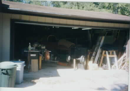 This is the where the in-progress airplane had
rested for several years prior to my buying it. Jerry (the previous owner) had
done some outstanding work over a several year period, but just lost the time
and interest to complete it.
This is the where the in-progress airplane had
rested for several years prior to my buying it. Jerry (the previous owner) had
done some outstanding work over a several year period, but just lost the time
and interest to complete it.
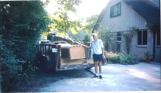 This is a picture of
Jerry standing in front of his creation. I've just gotten it loaded onto a
rented trailer and am ready for the trip back home to San Antonio from
Houston.
This is a picture of
Jerry standing in front of his creation. I've just gotten it loaded onto a
rented trailer and am ready for the trip back home to San Antonio from
Houston.

This is the picture of a man who just bought an airplane!
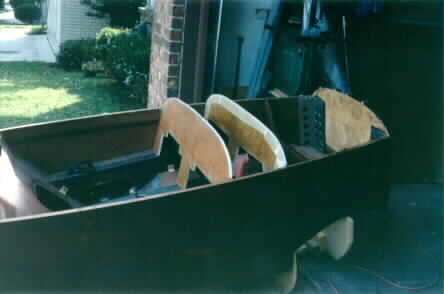
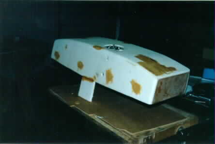
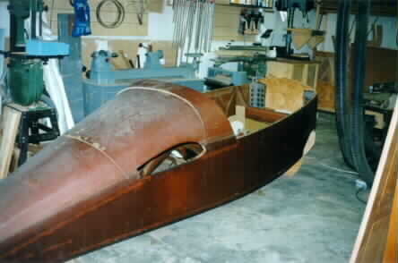 This picture shows the fuselage in the "Boat" stage.
This is pretty much how I got it, no consoles, instrument panel, or forward
bulkhead was installed. Ditto the header tank, firewall, etc; The wing and
canard were finished, though.
This picture shows the fuselage in the "Boat" stage.
This is pretty much how I got it, no consoles, instrument panel, or forward
bulkhead was installed. Ditto the header tank, firewall, etc; The wing and
canard were finished, though.
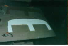 This is how the bulkhead and instrument panel
started out... bare Clark foam cut to the approximate shape required.
This is how the bulkhead and instrument panel
started out... bare Clark foam cut to the approximate shape required.
I learned a LOT while building the instrument panel, namely, don't follow the plans!
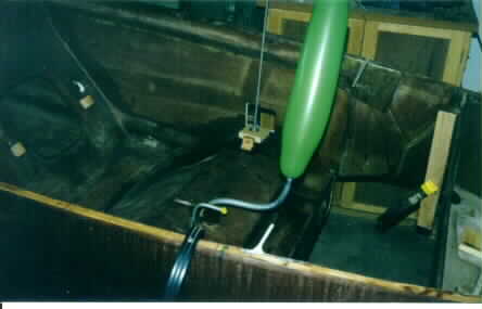 This is proof positive that the main fuel tank is
air-tight. I left the balloon aired up for about 6 hours.
This is proof positive that the main fuel tank is
air-tight. I left the balloon aired up for about 6 hours.
I call this my "Happy Dragonfly" picture. Get it?
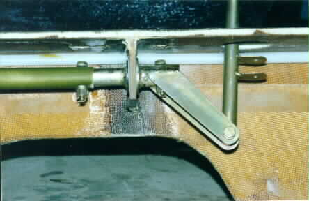 This is actually one of the first things I did on our
new aircraft-to-be. This is the passenger joystick installation, which is housed
in the right side console. (armrest)
This is actually one of the first things I did on our
new aircraft-to-be. This is the passenger joystick installation, which is housed
in the right side console. (armrest)
Completing and installing the consoles (there are three: right, left, and center) was high on the list of priorities because so many other things depend on their placement. (instrument panel, and forward bulkhead)
 This is the first test fit of the instrument panel and
forward bulkhead.
This is the first test fit of the instrument panel and
forward bulkhead.
This
picture has me doing the first mockup of the header tank. The header tank is a
small tank that "relays" fuel to the engine from the larger main tank, and
augments the main fuel tank capacity.

I cut out pieces of 1/2" Clark Foam to match the pattern I made from cardboard (in the background). I then layed-up 2 wet coats of 6oz. BID on the inside of the pieces, using peel-ply on all of the areas that would be joined in the future..
After this initial lay-up was done, I used small dabs of hot glue to hold the floxed and epoxied joints together.
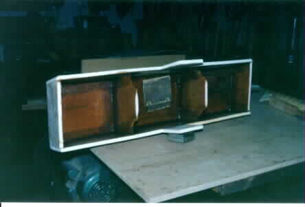 This is the result of the previous step. I was not
concerned with weight at this point, I just wanted to ensure that there was a
really wet layer of epoxy over the whole inside. To ensure that it's fuel
proof)
This is the result of the previous step. I was not
concerned with weight at this point, I just wanted to ensure that there was a
really wet layer of epoxy over the whole inside. To ensure that it's fuel
proof)
The patch of peel-ply on the inside center is where the fuel level sender mount ring will be installed.
 This shows the outside of the header tank, prior to the
exterior glass work. You can see the fuel level sender is installed at this
point.
This shows the outside of the header tank, prior to the
exterior glass work. You can see the fuel level sender is installed at this
point.
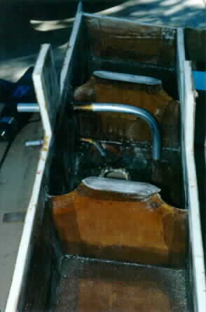 Here is the inside of the header tank, with the overflow
and vent tubes installed. The filler tube and fuel supply tube are installed
later.
Here is the inside of the header tank, with the overflow
and vent tubes installed. The filler tube and fuel supply tube are installed
later.
The little flat "feet" at the bottom of the center dividers are to bond the bottom to. All of the sides will have these flanges installed.
Click here to continue on!![]()
Click here to go home!![]()

