
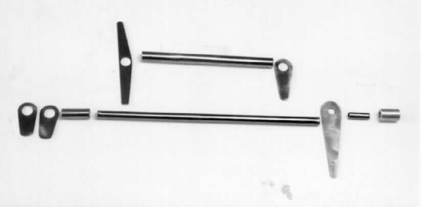
Here are the individual components. All are from 4130 steel.
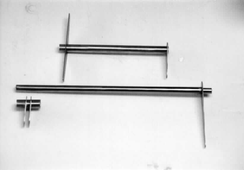
Here are the components before being welded
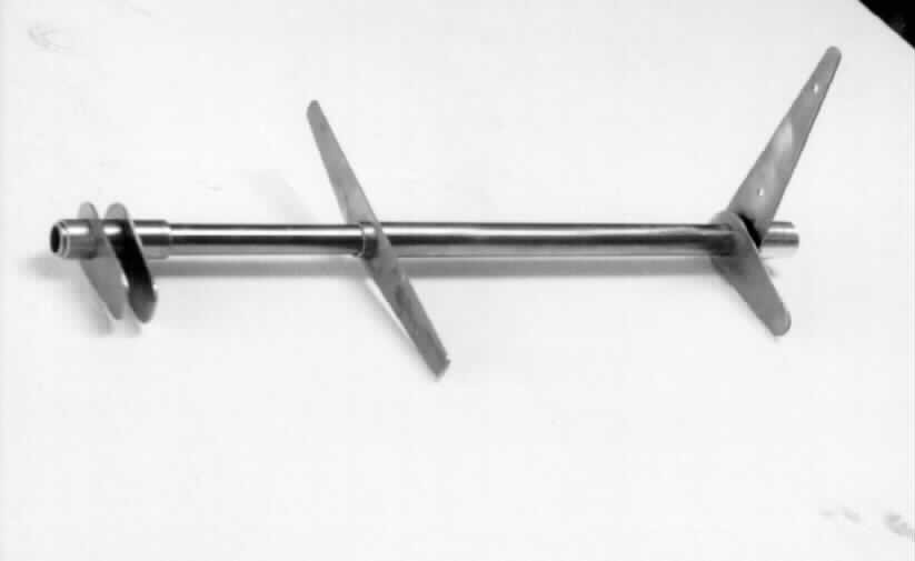
Another view of the pre-weld stage
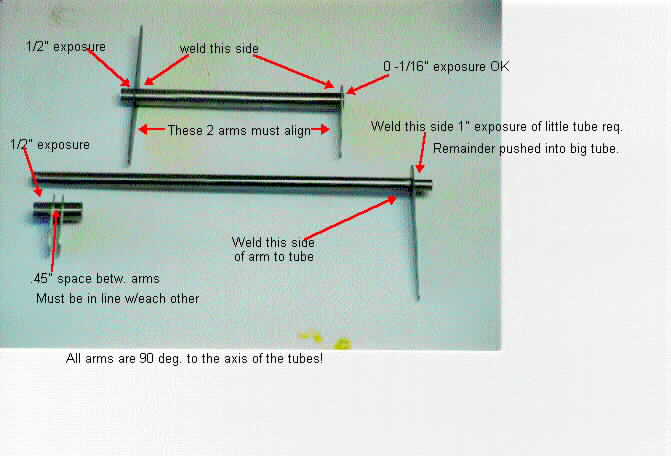
This is self explanatory
In order to get a good, smooth machine fit between the two shafts (the aileron control shaft rides inside of the servo / trim shaft) I chucked the aileron shaft in my wood lathe, then polished the OD with fine emery cloth and oil till it was super smooth, Then, I honed the inside of the servo shaft with 180 grit paper wrapped around an arbor, powered by a hand drill, using LOTS of light oil till the inside of the shaft was mirror smooth. Once I did this, I applied a light film of STP engine oile treatment to the two shafts, slid them together... the fit is incredible! It feels like a very, very smooth bearing.
This is the assembly as it will bolt to the wing (all the exposed surfaces will be zinc chromated) All the control rod / rod end thru-bolt holes have yet to be drilled.
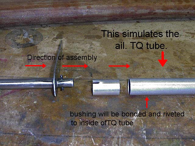
In this view you can see how the "stub" will plug into the aileron torque tube. There is an aluminum bushing that will be bonded and riveted to the inside of the aileron torque tube, and the stub end of the bellcrank will key into that.
I finally got around to working on the aileron controls again. Here's some pictures.
After thinking of how I wanted to control my ailerons, I decided that I wanted to share the torsional load imparted by the control arm with the aileron TQ tube. (instead of relying solely on the rib) So I decided to install a "keyed" bushing into the TQ tube. What this means is that after I bond and rivet the bushing into the TQ tube, the TQ load will be shared by the plywood rib, and the TQ tube running the span of the aileron.
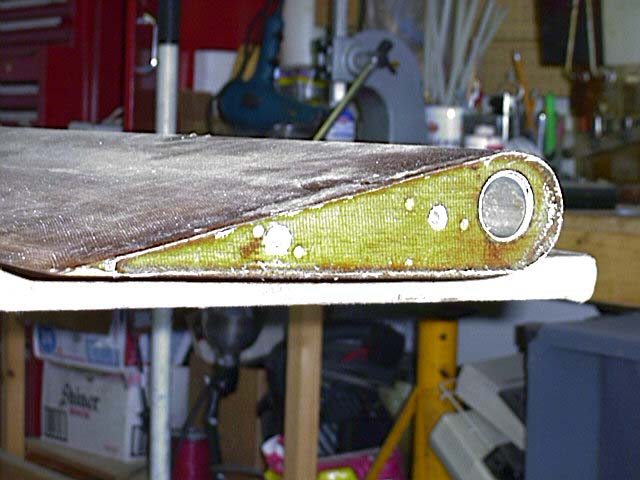
 The first step
in converting my ailerons for use with the new and improved controls is to saw
the aluminum TQ tube flush with the end of the aileron. Then, remove the foam to
a depth of 1/2". (this will give room for the installation of the plywood "rib"
and the 4130 control arm, and still allow the mount bolts to be flush with the
end of the aileron)
The first step
in converting my ailerons for use with the new and improved controls is to saw
the aluminum TQ tube flush with the end of the aileron. Then, remove the foam to
a depth of 1/2". (this will give room for the installation of the plywood "rib"
and the 4130 control arm, and still allow the mount bolts to be flush with the
end of the aileron)
 The next
step was to cut the plywood rib to shape. Its very important that it fit the
cavity perfectly.
The next
step was to cut the plywood rib to shape. Its very important that it fit the
cavity perfectly.
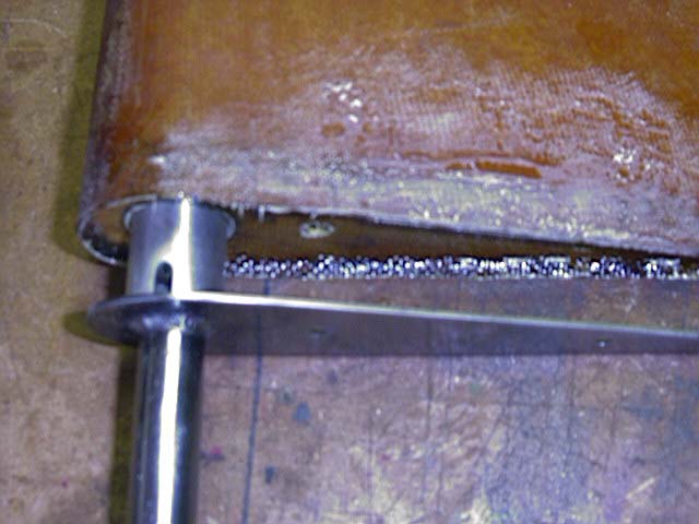
 Here is the rib,
the self locking nut plates are riveted to it, and the 4130 control arm is
bolted in place. In place inside of the torque tube is the aluminum bushing and
stub (where the yellow clay is) The assembly needs to be floxed in with the
bushing and stub in place, as this ensures that the assembly is properly
located.
Here is the rib,
the self locking nut plates are riveted to it, and the 4130 control arm is
bolted in place. In place inside of the torque tube is the aluminum bushing and
stub (where the yellow clay is) The assembly needs to be floxed in with the
bushing and stub in place, as this ensures that the assembly is properly
located.
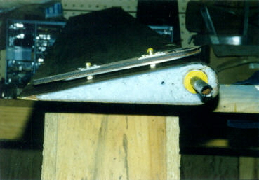
 This is
the near-completed aileron end. After the rib is floxed in, I closed out the end
of the assembly with one ply of 10 oz.
This is
the near-completed aileron end. After the rib is floxed in, I closed out the end
of the assembly with one ply of 10 oz.
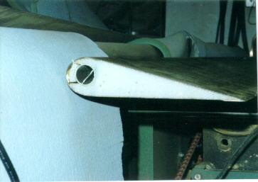
I'll cut the aileron just aft of the last rivet, which will become the servo-trim tabs. (still to come!)
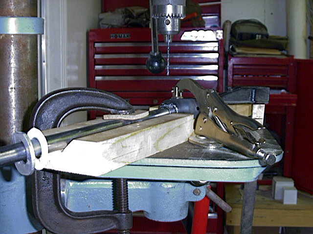
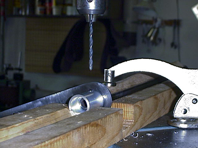 This is how
the bushing and tube get drilled. They are held very tightly in the "V" of the
notched board. They have also already been pilot drilled.
This is how
the bushing and tube get drilled. They are held very tightly in the "V" of the
notched board. They have also already been pilot drilled.
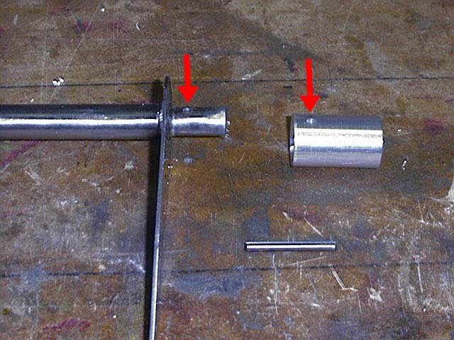 Here the
control arm stub and the bushing have been drilled for the spring steel pin. The
bushing and stub must be drilled while they are assembled, so the hole aligns
perfectly. The hole in the bushing will be made into a slot, while the pin gets
permanently inserted into the stub.
Here the
control arm stub and the bushing have been drilled for the spring steel pin. The
bushing and stub must be drilled while they are assembled, so the hole aligns
perfectly. The hole in the bushing will be made into a slot, while the pin gets
permanently inserted into the stub.
This pic is pretty self explanatory. Notice that the bushing has been slotted; the fit between the slot and pin is nice and snug..also very important.
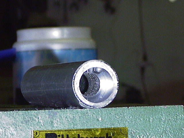
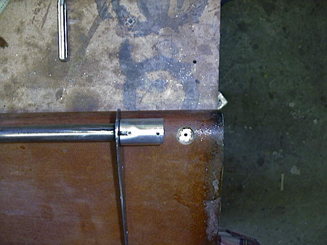
this is the outboard end of the bushing... counter bored .75 inches deep so that the same rivets used on the aileron and elevator thimbles can be used here.
This is the inboard face of the bushing, before it was slotted. The chamfer is to allow for the weld bead on the stub of the control arm. (The inside is perfectly machined, but I didn't clean the swarf out before I took the picture)
 Here
is how the assembly bolts together. Two -3 bolts thru the control arm hold the
arm to the rib.
Here
is how the assembly bolts together. Two -3 bolts thru the control arm hold the
arm to the rib.
The only thing I have to do now is bond and rivet the bushing into place.
This is a piece of scrap tube, the same dimensions as that used in the ailerons, and a scrap piece I machined to the same dimensions as those of the bushing. This was a "confidence" exercise to ensure that the rivets I used to hold everything together were actually gonna do the job.
 Here's the assembly, all ready to get bonded and riveted in
place.
Here's the assembly, all ready to get bonded and riveted in
place.
 Here's a
closeup of the installed socket. I used rivets and Hy-Sol to hole everything
together.
Here's a
closeup of the installed socket. I used rivets and Hy-Sol to hole everything
together.
The fit and function of the bellcranks is very positive, with absolutely no play or slop.
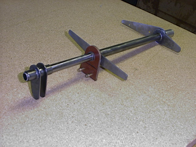
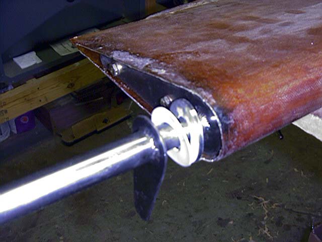 Here the
control arm is bolted on. This picture shows the components that allow the servo
/ trim tab control bellcrank to rotate around the aileron control
bellcrank.
Here the
control arm is bolted on. This picture shows the components that allow the servo
/ trim tab control bellcrank to rotate around the aileron control
bellcrank.
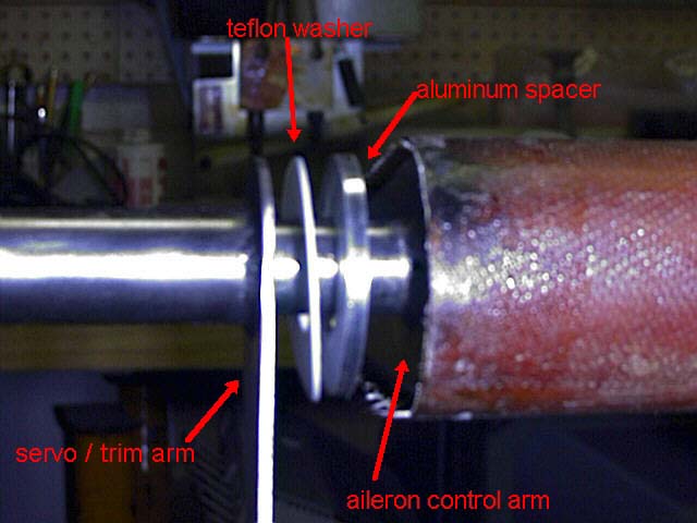 These are
the components that provide the clearance between the servo control arm and the
aileron. The aluminum spacer is step drilled.. one side is bored 3/4", the other
is 5/8"... this is to allow the spacer to straddle the weld bead, but still ride
concentrically on the shaft.
These are
the components that provide the clearance between the servo control arm and the
aileron. The aluminum spacer is step drilled.. one side is bored 3/4", the other
is 5/8"... this is to allow the spacer to straddle the weld bead, but still ride
concentrically on the shaft.
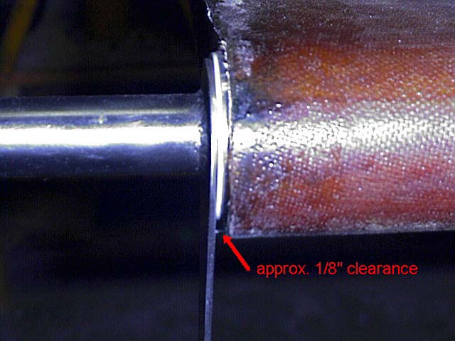 Clearance
between the servo control arm and aileron is approx. 1/8"
Clearance
between the servo control arm and aileron is approx. 1/8"
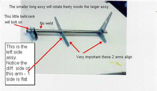
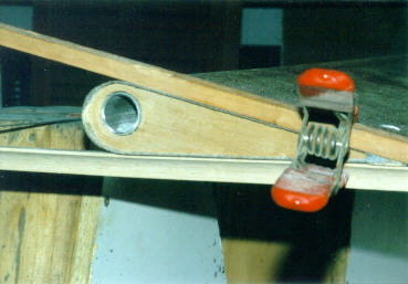
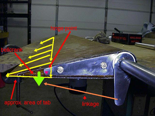 This is how
I plan to actuate my servo / trim tabs. The indicated bellcrank ratio is just
for illustrative purposes, and will be adjusted to accomodate the proper throw
of the tab.
This is how
I plan to actuate my servo / trim tabs. The indicated bellcrank ratio is just
for illustrative purposes, and will be adjusted to accomodate the proper throw
of the tab.
 This is how all
of the thru-bolt holes get drilled.
This is how all
of the thru-bolt holes get drilled.
First, the "V" block is centered under the pilot drill. Then the tube to be drilled gets clmped in place.
The pilot hole, then the slightly undersized final hole get drilled. Then, the last step is to ream the hole to the final dimension.
The shank of a -3 bolt is exactly .1880" in diameter. The reamer I run through the holes is .1885". This gives an excellent fit, with no slop.
All these steps are done while the whole assembly is firmly clamped.
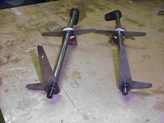
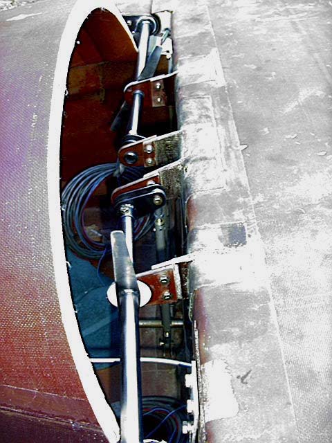 This is the
current state of affairs. The ailerons go up and down when I move the control
stick... momentous occasion!
This is the
current state of affairs. The ailerons go up and down when I move the control
stick... momentous occasion!
That's it for now! Click HERE or hit "Back" on your browser
