
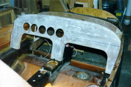
 This is the cockpit with the instrument panel and
forward bulkhead sitting in place. You can see that the fuel level sender is
installed in the main tank, between the passenger's knees. The aileron trim
mechanism is installed in the center console.
This is the cockpit with the instrument panel and
forward bulkhead sitting in place. You can see that the fuel level sender is
installed in the main tank, between the passenger's knees. The aileron trim
mechanism is installed in the center console.
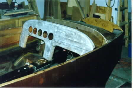 Here you can better see the relationship between the
forward bulkhead and the header tank. (barely!)
Here you can better see the relationship between the
forward bulkhead and the header tank. (barely!)
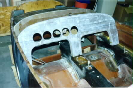 And yet another view of the cockpit area. There will be
more holes drilled in the instrument panel, but they can be done with a hand
drill. These 3.5" holes were cut with a hole cutter on the drill press.
And yet another view of the cockpit area. There will be
more holes drilled in the instrument panel, but they can be done with a hand
drill. These 3.5" holes were cut with a hole cutter on the drill press.
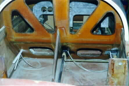 This shows the aileron control torque tube as it exits
the seat back bulkhead. After exiting the bulkhead in the center, there is a
push-pull tube that laterally connects the center torque tube with the right
side torque tube. This is one half of the dual flight control setup. After this
point, the aileron torque tube proceed aft, where they pass through a
"Reflexer." More on this later.
This shows the aileron control torque tube as it exits
the seat back bulkhead. After exiting the bulkhead in the center, there is a
push-pull tube that laterally connects the center torque tube with the right
side torque tube. This is one half of the dual flight control setup. After this
point, the aileron torque tube proceed aft, where they pass through a
"Reflexer." More on this later.
The large white conduit on the left is for electrical wires, the smaller is for the left side rudder cable.
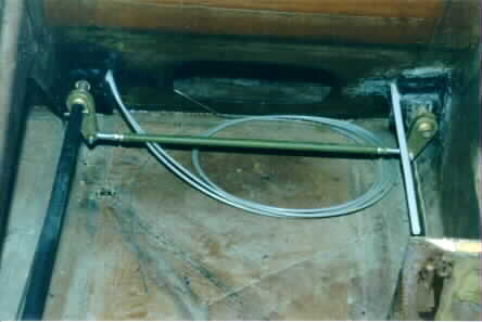 This shows the two torque tubes linked by the push-pull
tube. The white tube on the right will carry the right side rudder cable. The
two small white tubes in the center will carry the aileron trim cables from the
trim mechanism.
This shows the two torque tubes linked by the push-pull
tube. The white tube on the right will carry the right side rudder cable. The
two small white tubes in the center will carry the aileron trim cables from the
trim mechanism.
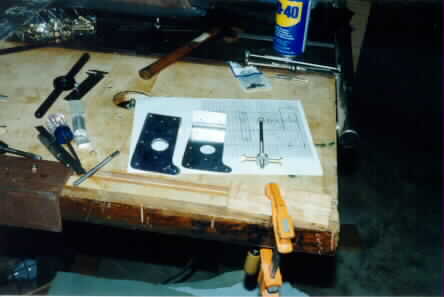 Here I'm constructing the reflexer control mechanism. I
decided to use a screw driven mechanism rather than a cable or electric
device.
Here I'm constructing the reflexer control mechanism. I
decided to use a screw driven mechanism rather than a cable or electric
device.
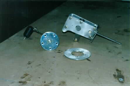
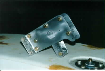
This is the completed mechanism, along with the fuel level sender and the mount ring. The reflexer control will get mounted in the left side of the instrument panel, ahead of the throttle control. The ring is of 1/8" aluminum, with self locking nutplates riveted in. I installed one ring in the header tank, and one in the main tank.
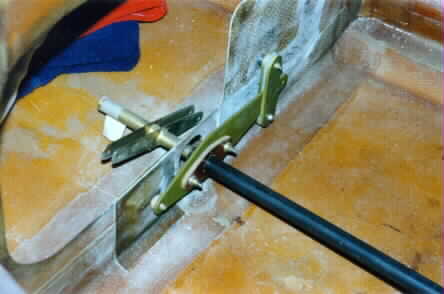 This is the reflexer mechanism.(Thanks Bill Gwinn!) It
is simply a 1/8" aluminum lever, with a phenolic bearing for the aileron torque
tube to pass through. On the right side of the picture, you can see that it's
vertical motion is dampened by two sliders. These are also 1/8" aluminum, with
teflon pads riveted and bonded in place. It slides very smoothly, but does
require a little effort.
This is the reflexer mechanism.(Thanks Bill Gwinn!) It
is simply a 1/8" aluminum lever, with a phenolic bearing for the aileron torque
tube to pass through. On the right side of the picture, you can see that it's
vertical motion is dampened by two sliders. These are also 1/8" aluminum, with
teflon pads riveted and bonded in place. It slides very smoothly, but does
require a little effort.
The aileron torque tube is made from 5/8" x .058 wall 4130 steel. This is a change to the plans (called for aluminum) but Justin Mace recommended it after he learned that his aluminum tube was actually winding up during "vigorous" flight manuevers!
The aileron horn is not yet complete. I'm going to weld another arm to the end so that I can cross my aileron push-pull tubes. This will eliminate the need for a set of mixers.
 Here's another shot of the completed reflexer
actuator.
Here's another shot of the completed reflexer
actuator.
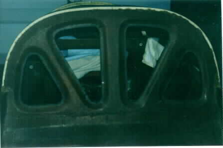 This shows the seat back bulkhead as the plans call for
it to be built. I didn't like it, cause I want to have a small baggage area aft
of the seat.
This shows the seat back bulkhead as the plans call for
it to be built. I didn't like it, cause I want to have a small baggage area aft
of the seat.
So I modified it.
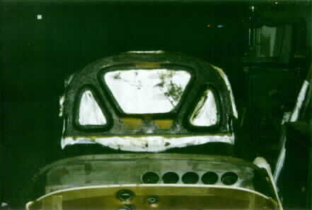 This is an in-progress picture of the new seat back
bulkhead. I removed the center vertical support, added two layers of 10oz BID to
the front face, and added 4 layers of 10oz, 6" wide BID tape to the back /
underside of the hoop. I also recontoured the lower section of the center
area.
This is an in-progress picture of the new seat back
bulkhead. I removed the center vertical support, added two layers of 10oz BID to
the front face, and added 4 layers of 10oz, 6" wide BID tape to the back /
underside of the hoop. I also recontoured the lower section of the center
area.
Click here to go back![]()

