


My Homepage
X-Gun: 3-Stage Optically Triggered Coil Gun
Big Gun: High Energy 3-Stage Coil Gun
Permanent Magnet Repulsion Coil Gun still in the making
Event Counter: High Speed Clock to Determine Projectile Velocities
Results: Check out some quantitative coil gun results on the high energy coil gun
The concept is pretty easy to understand unless your name is Kurtz or Matt. An electric current is passed through a hollow coil of wire inducing a magnetic field in the vicinity of the coil. Anything "magnetic" that is near the coil experiences an attractive force towards the center of the coil. If the current through the coil can be switched on and switched off at just the right time, the magnetic object can be accelerated right through the hollow coil towards a target or another coil system. A series of these coils and switches may be arranged on a linear barrel to produce a coil gun.
The projectile can be pretty much anything that will stick to a magnet and fit in the barrel. Nails, screws, segments of clothes hanger all work ok. Long stuff works well, round stuff does not. The more it sticks to a magnet the better. And remember, the lighter it is, the faster it will go!
The barrel's job is basically just to hold things in a straight line. When choosing a barrel it is important to take several factors into account. If you want to use optical sensors to trigger additional coils, you're going to want something that is essentially transparent to the light that your sensors use. Glass and plastic are have low absorptivities in the infrared region and work well. Metal barrels restrict the field experienced by the projectile because eddy currents are produced in the conductive barrel material (unless you can find a metal that is not conductive!) You must also think about the forces that will be acting on your barrel. When the coils are energized, they compress and will smash a glass or plastic barrel if your gun is really juiced up.
The coils must be made of magnet wire to produce the large magnetic field you need to get the projectile zooming. Magnet wire is used to make electromagnets (like relays) and electric motors. An excellent source of magnet wire are microwave cooling fans. The fans are easy enough to get out of the microwave, but getting the wire out of the fan motor is a bit tricky to do. The wire is wound on a coil around a squarish coupling made of iron sheets. You can remove a few of the iron sheets with a small flat screw driver and a hammer. After several of these sheets are removed, the entire coil of wire can be dislodged leaving you with a hundred feet or so of nice wire. With significantly more effort, the thick magnet wire in the main microwave transformer can removed utilizing the same technique of transformer destruction. Getting the wire is the tough part, next you just wind up the coils. The coils don't need to be wound in any certain direction for good coil gun action. The size of the coil influences the magnetic field it puts out. Usually the larger the coil, the larger the field for a given current it's passing. But the longer your coil is, the more resistance and inductance it has. This is going to cut down the current it will pass at a given voltage, so there is an optimum coil size/length.
The capacitors store and release the crapload of energy you need to get your projectile moving. Since the magnetic field is greatly dependent on the current you can pass through the coil in a small amount of time, you are going to want as much voltage as you can manage across your coils and capacitors. So the capacitors you use are going to depend on how you're going to charge them up. With a only a 9-Volt battery as a power supply, capacitors rated for any more than 9-Volts are just a waste. If you are going for low voltage, you'll need a lot of capacitance (several thousand uF). Or if you go the high voltage route, you need a lot less capacitance at a higher voltage rating. Capacitors out of camera flash circuits work especially well for this application because they were designed to discharge rapidly through the flash tube. Flash capacitors are typically rated for 300-350 working volts at around 200-500 uF which is plenty for a fun coil gun. Depending on the properties of your gun (coil size, operating voltage), increasing the capacitance of your capacitors could actually SLOW down your shooter. If the capacitance is too high, the coils will be energized too long and they will slow down the projectile or even prevent it from passing at all. So where am I supposed to get capacitors from flash circuits you butt-licker? Well I guess you can con the people at the mall photoshop into giving you disposable camera carcasses. I find them in a the trash or at goodwill.
You can charge your capacitors with any DC source, a computer power supply box, a car battery charger or a cactus (according to McGuyver). To achieve some major high voltage, you're going to need to make or steal a high voltage power supply. An easy one to make is the transistor driven flyback transformer power supply. The parts are pretty easy to come by and you can't beat the output voltage of up to 20,000 volts! Here's the link to the high voltage flyback transformer information flyback. You do need to be careful when you use this kind of charger on your capacitors as it could easily surpass the voltage rating on your caps so you need to monitor the capacitor voltage while charging. I recommend a cheap analog VOM for this because you can dedicate it and also a digital VOM would get fried if you accidentally overloaded it! Also, the flyback circuit will only give you 1-2 mA, so if you are making a big gun, say > 1500 uF total capacitance you are going to want a more powerful supply or you will spend all day trying to charge up your caps.
If you only have a one coil system, you can fire it with just a switch with a high surge or current rating. If you plan on having more than one stage or coil, you'll need a way to switch on your capacitors quickly at just the right time. In order to get the switching speed you'll need for a nice gun, you'll need some silicon products. Most coil gunners who employ the capacitor design use SCR's (Silicon Controlled Rectifiers) to dump the capacitors through the coils. The SCR stays open (no current flowing) until it receives a signal of positive voltage to the gate terminal. Once it gets gate signal, it conducts in one direction until the current drops down below the threshold current level for the specific SCR. There is no stopping the SCR after it's begun conducting, so it's ideal for capacitive discharge circuits which stop themselves (when completely discharged). SCR's are sold by their voltage and current maximum ratings. When choosing and SCR, make sure that you won't exceed its maximum voltage rating and choose a SCR with as high of a surge current rating as possible. Most SCR's can handle a lot more current as a short surge than what they are rated for. So to save money, look for the surge ratings rather than the nominal current rating. The currents passing through the coils are quite substantial. At 300 volts and a coil resistance of only an ohm or two, more than a hundred amps will be passed through the SCR for a brief time.
I also have messed around with a transistor switched coil gun (rather than SCR). I figured that with a transistor switcher, I could have a constant DC power source across the coils for a longer amount of time (longer than a capacitor discharging) which would hopefully increase the force that the projectile would experience. This is the design that I came up with. For coil power, it uses a DC power supply constructed from a VARIAC (variable voltage transformer) whose output was then rectified and fed through a large capacitor to take out some of the ripple. So I ended up with a 0-150 Volt DC power supply for the coil power. I used a break-beam optic sensor so the transistor would conduct the entire time the beam was broken and then stop conducting when the beam had been restored. Here is the system I ended up with transistor driven. But I could never get as much acceleration out of the transistor drivers as a simple capacitor/scr system. I think that I could just not get enough juice through the coil operating at only 150 Volts maximum???
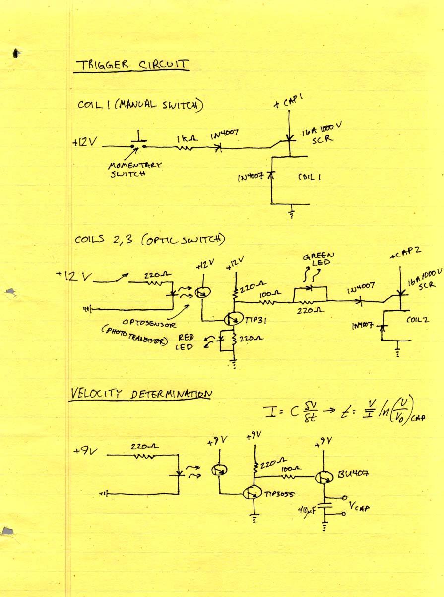
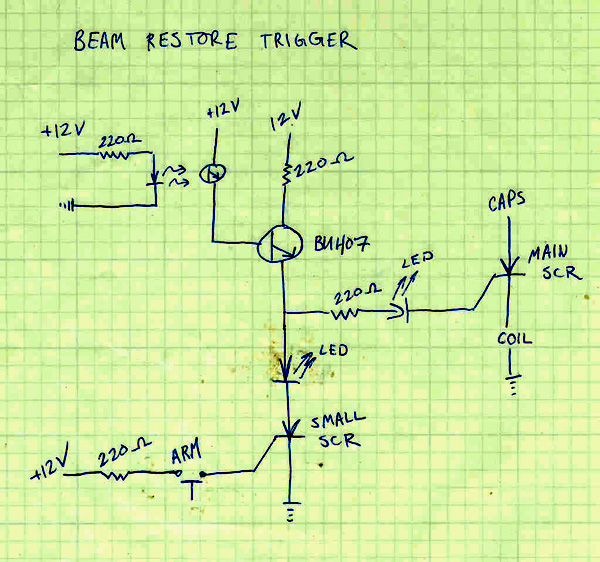
If you have more than one coil, the trigger circuit and timing is the most important part of this project. If the timing is off, you could end up stopping or even shooting your projectile backwards! I have always used optical triggers so my knowledge on other trigger systems is essentially zero (Sorry!). But I do have a bunch of stuff on optical triggers. With optics you have a couple of options. You can have your SCR fire when the beam is broken, when it is restored, or fired at a variable amount of time after the beam is broken or restored. Here are some diagrams of optical triggering circuitry. Here is a circuit that manually discharges the first capacitor, switches the SCR's as the beam is broken, and also a circuit to determine the projectile's velocity (more about this later). Here is another one that fires the SCR when the beam has been restored (after the projectile passes through). The X-Gun utilizes a modified restored beam circuit which works very well. But don't forget the BYPASS DIODE!
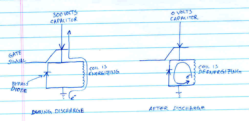
In order to protect your switching units (SCR's) from over voltage caused by your coils, a bypass diode MUST MUST MUST be installed. This diode is placed in parallel with your coil. The polarity is biased so that the main capacitor current cannot pass through the diode, but the "after current" created by the coil can dissipate itself. here is the correct polarity diagram. Helping dissipate the current as fast as possible also allows the projectile to exit the coil with maximum velocity so several bypass diodes are commonly used in coil gun projects.
Measuring the projectile velocity is very important when you want to brag quantitatively to your friends,
 but is not an easy thing to do! I once tried to shoot it straight ahead and tried to measure its
trajectory and back out the velocity from kinetic motion equations. This did not work, as it was very difficult to get accurate measurements. Another method of determining the velocity is electronically. I don't have any fancy expensive equipment so I made this device that I can use to time the projectile through the barrel of my coil gun. The circuit diagram is above in the trigger circuit section. It works like this: I used
another optic sensor and some transistors to charge a capacitor. As the beam was broken with the projectile, the transistors allowed a moderate current from a battery to charge up a 410 uF capacitor.
The voltage across the capacitor is proportional to the charge time which is inversely proportional to the velocity of the projectile. In order to calibrate this circuit (don't trust the equations) I set up another identical barrel that is mounted vertically. I dropped the same projectile I use for the gun down the barrel at different starting heights and measured the initial and final voltage across the capacitor. I then used gravitational kinetic equations to
determine the correct velocity for the different heights. Then the data were plotted with a logarithmic fit. Anyhow, for the projectile that I was using, the velocity is approximately 21/ln(v/vo) meters per second.
but is not an easy thing to do! I once tried to shoot it straight ahead and tried to measure its
trajectory and back out the velocity from kinetic motion equations. This did not work, as it was very difficult to get accurate measurements. Another method of determining the velocity is electronically. I don't have any fancy expensive equipment so I made this device that I can use to time the projectile through the barrel of my coil gun. The circuit diagram is above in the trigger circuit section. It works like this: I used
another optic sensor and some transistors to charge a capacitor. As the beam was broken with the projectile, the transistors allowed a moderate current from a battery to charge up a 410 uF capacitor.
The voltage across the capacitor is proportional to the charge time which is inversely proportional to the velocity of the projectile. In order to calibrate this circuit (don't trust the equations) I set up another identical barrel that is mounted vertically. I dropped the same projectile I use for the gun down the barrel at different starting heights and measured the initial and final voltage across the capacitor. I then used gravitational kinetic equations to
determine the correct velocity for the different heights. Then the data were plotted with a logarithmic fit. Anyhow, for the projectile that I was using, the velocity is approximately 21/ln(v/vo) meters per second.
In order to more accurately measure the projectile velocity I've opted to make a high speed event timer. The circuit diagram and explanation can be found here. This timer displays how long the projectile blocks a beam/photo detector. The velocity the projectile is traveling at is simply the length of the projectile divided by the time it blocks the beam.
The author assumes no liability for any incidental, consequential or other liability from the use of this information. All risks and damages, incidental or otherwise, arising from the use or misuse of the information contained herein are entirely the responsibility of the user, have a nice day!
Last updated: 6/28/02