
Link back to my Homepage
Link to the main Coil Gun page
Link to the low energy X-Gun page
Link to the high energy coil gun page
Link to the permanent magnet repulsion coil gun page
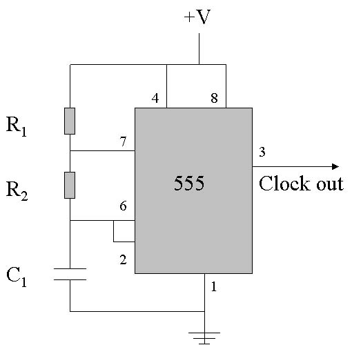
Clocks (oscillators) can be made from many electronic devices. Crystals, LC, logic gates and clock IC's can all be used. The clock circuit that I made utilizes a 555 timer IC (integrated circuit). For this application, the clock runs continuously, but the output of the clock is only "counted" when the correct signal from the trigger circuitry is also present.
The 555 clock puts out a squareish wave at an operating frequency determined by the values of two external resistors and one capacitor. The clock frequency should be set to put out a pulse in fractions of seconds divisible by ten (like 10 times/second or 100 times/second...) so that the display represents the actual time. The oscillation time of the 555 IC can be calculated by the following equation:

This equation will get you in the ball park, but you really need an oscilloscope to tune-in to the right frequency. The 555 timer diagram can be seen here.
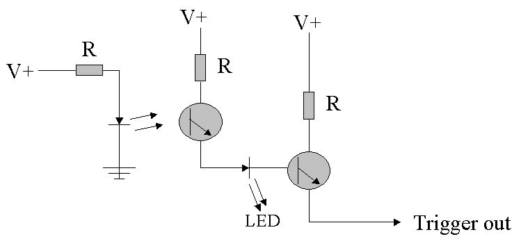
The trigger circuit's job is to start and stop the counter during the event being investigated. The trigger circuitry can vary greatly depending on what your event is, and how it can be sensed. For the coil gun application, photo-detectors are an obvious choice for the triggering. To measure the velocity, the distance the projectile travels must be known in addition to the time it took to travel that distance. If the sensor is a single photo-transistor/diode pair, the distance the projectile travels during the time the beam is interrupted is simply the length of the projectile.
The signal from the trigger is processed by amplification, inversion or whatever means necessary to electronically control the counter. But however the signal is used, it is important to include a Schmitt trigger as part of the signal processing. The Schmitt trigger "cleans up" noisy signals by outputting a clean, fast-rising pulse that is easily detectable by digital circuitry. It also helps filter out noise from ambient lighting conditions. An example of my trigger circuitry can be found here.
There are many ways to count and do arithmetic with integrated circuits. That is there are many IC's that do that kind of thing for you; all you have to do is hook them up correctly. For counting, you can use decade counters (they're called decade because they can count to 10). In addition to signaling out the binary (only 1's and 0's) digit sum, decade counters will also output one pulse for every ten pulses it gets. This is very useful if you want to display more than one digit of information.
The information is represented in binary digits by the counter chip. This information can now be decoded and displayed on 7-segment displays (like an alarm clock face). You could also of course just read the binary code and figure out what decimal number it corresponds to. But basically, the decoder's job is just to take the binary number and convert it so you can read it off a 7-segment display.
Clocks
I chose to have two clock frequencies, 100 kHz and 10 kHz to give me a wider timing range. This is accomplished by having two independent clocks on board. Each of the clocks are tuned to the correct frequency by a 1k variable resistor and an oscilloscope. The display reads "0.00" in the high frequency range and "00.0" in the low range. By shifting the decimal place like this, the display always reads in milliseconds.
Triggering
This event counter is capable of triggering by both "low" and "high" signals depending what trigger mode it is in. This means that it will start counting when the trigger input goes to +5 V or to ground, whichever I like for what I am testing. Typically, I use a single photo-transistor/diode pair. So when the beam is interrupted by the projectile, the output from the photo-transistor will go from high to low so I would use the "low" trigger input. When the projectile passes, the photo-transistor output will go "high" again and stop the counting. A Schmitt trigger is also incorporated into the event counter to help clean up the signal from the trigger circuitry.
Counting
For my system, the pulses from the clock and the signal from the trigger are sent through an "AND" logic gate. This means that the output of the logic gate will be "high" only when it gets a pulse from the clock AND the correct signal from the trigger system. The output from the AND gate is fed into the counters.
The particular counting chip that I used is the 7490 decade counter IC. It can count from 0-9 and outputs the count on four pins in binary encryption (only 1's and 0's). I chose this IC because I had lots of information on it, although there are many other newer and better counters. There's really not too much to say about counting. Pretty standard in this department but it does include a "over-range" LED. At 100 kHz it's pretty tough to say if the counter has "rolled over" meaning that it has counted more than three digits worth (>999) and has started counting all over again. The over-range light tells me that I have counted past the range of the display, so I know that the display is not correct. Another important function is to be able to "reset" the display. That would be helpful, eh? It's pretty easy with the counter chip, you just put a momentary switch across a couple of pins and it sets the displays back to "0.00" when you press the button.
Display Driver
I am using a 7-segment display decoder/driver 7447 IC. The 7447 driver is really meant for common anode displays meaning all the display LED share the same anode or + pin. To run a common cathode display, you could modify the circuit or buy a driver for common cathode displays. Again there are hundreds of display drivers, this is just the one that I happened to have information on.
Power Requirements
I've chosen to run off a 9-V battery for simplicity and portability. Since the chips I have were made years and years ago, they are pretty picky about operating voltage. The counter and display chips will only work at like 4.5-6V so I use a LM7805 5-V voltage regulator. The circuit consumes approximately 350 mA during operation.
Last updated: 5/20/03