
The capacitor bank consists of six (6) 5100 microfarad electrolytic caps rated for 350 VDC. Each of the three stages utilize two of these capacitors wired in series providing 2550 microfarads at 700 VDC. The voltage of the capacitors is monitored via a digital voltage meter (DVM). The total peak energy storage for this system is 1874 Joules, the same amount of caloric (not mass) energy found in 4.7 tablespoons of SKIPPY peanut butter. For reference, my other coil gun's peak energy was 55 Joules or 0.14 tablespoons of peanut butter. Convenient it would be if this could be fueled with peanut butter, but most certainly messier. Anyways, the peak instantaneous power output at 700 volts and a coil resistance of 0.4 ohms is 1.225 megaWatts. That's the power equivalent of 1,225 medium size microwave ovens running simultaneously! These capacitors weigh nearly 20 pounds and were purchased at the SLAC salvage yard.
Barrel
The barrel is 20 inches of 3/8" OD SS tube. The inside diameter is slightly
larger than 0.25 inches. This material was chosen for its rigidity and its ability to withstand the strong magnetic contraction
forces exerted by the coils when they are energized. Although severe eddy currents are most certainly present due to the conductivity of steel, this is the most suitable material I have found. Stainless steel does have quite poor electrical properties, and the benefits of having iron in the flux path may more than negate the undesired effects of eddy currents. The barrel was scrap metal in the SLAC salvage yard.
Coils
The coils are wound over a few wraps of notepaper directly over the barrel. The notepaper provides a non-slippery surface to wind the coils on and it also allows the translation of the coils along the barrel. The coils are 1.5 inches in length, five layers of 16 gauge enamel-coated copper magnet wire. The wire was stripped from a microwave oven transformer after about an hour of smashing, hammering and cursing. The microwave was found in a dumpster in Palo Alto, CA. After they were wound, the coils (and my hands) were secured with quick-tite super glue and then wrapped with electrical tape. The coils have an approximate resistance of 0.4 ohms.


Projectile
Projectile is 0.25 inch diameter bolt shaft. The head and threads were hacked off with the disc grinder leaving an approximate length of 1.5 inches and a weight of about 8 grams. Power tools rule! I'm also going to try to fire Gillian's engagement ring out of this thing.


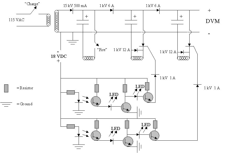
Switching
The first stage is switched via a heavy duty relay with a 24 VAC coil. The second and third stages utilize silicon-controlled rectifiers (SCRs) to accomplish the high speed switching needed to accelerate the projectile. The SCRs came from the SLAC salvage yard and the specifications for them are unknown. I machined a pair of mounting brackets from a 0.1 inch thick aluminum plate. After substantial abuse, these SCR's became non-functional and were replaced with a pair of 1400V 110A studs with a 400 amp surge rating. These SCR's were purchased through ebay for about $10 each.
Infrared diode and phototransistor pairs were used to sense the location of the projectile for triggering. A simple "break-beam" circuit was used to trigger the switching components. When the infrared beam is first engaged by the projectile, an inverted and amplified signal is sent to the corresponding SCR, discharging the capacitor bank through the coil. The sensor pairs were mounted directly on the barrel with the infrared beam passing through 0.1 inch diameter holes in the steel pipe. In order to drill the holes through the center of the barrel, I machined this aluminum clamp. The clamp secures the pipe and a pilot hole in the clamp allows a guided drilling path through the center of the barrel.


After installation, the infrared diode/phototransistor pairs were wrapped with several layers of black electrical tape to ensure that ambient lighting conditions would not interfere with sensing. The diode/phototransistor pairs came from a touch-panel circuit board that I purchased through e-bay for a few dollars.
The panel contained about 60 pairs of matched diodes and phototransistors. These units have a narrow deflection angle,
which, make them ideal for long distance sensing (up to a few inches) without the aid of additional optical components.
Coil Gun Photographs and Schematic


That milk crate sure has a lot more room for energy storage
capacitors...
Results: Tales of Destruction
Follow the links at the top of this page for the velocity results for this high energy coil gun.
The author assumes no liability for any incidental, consequential or other liability from the use of this information. All risks and damages, incidental or otherwise arising from the use or misuse of the information contained herein are entirely the responsibility of the user, have a nice day!
Last updated: 9/28/02