
|
|
||
|
25. A Human Skull - Modeling the Skull 1 |
||
 MODELER, MODELING THE SKULL Now you are ready to create a complex organic object using all of the skills you've learned. You must first have done tutorial #23 and #24, 'A Human Skull - Image Preparation 1 & 2'. You must have saved the three prepared image files that you created as front.bmp, back.bmp and right.bmp, dimmed the images and loaded them as backdrops in the three LightWave viewports. You would have created those three files by downloading the skull1.zip archive and following the last two tutorials. If you have completed doing that, you can continue. Load 'skull.lwo' into Modeler. Press 'd' key to bring up the 'Display Options' panel. click the 'Backdrop' tab and under the 'Presets' drop-down menu select 'Load Backdrop'. The three images will appear in their viewports. Click 'OK'. Zoom the size of the head by pressing the '.' key a few times.  MODELER, SLICES THROUGH THE HEAD There are many ways to create a head. Some do it the pumpkin way, where all polygons taper to the top of the head like a pumpkin would. The red dot would be the nose.  And, others turn it sideways so the connection points are over by the ears. This allows the head to be drawn as contours. With the contour method, the lines look like they were sliced through the object like one might slice cheese in parallel lines. The red dot would be the nose.  The contour method is the method I like to use. MODELER, BUILD A PIECE AT A TIME Now that you have seen those, forget them. I don't want you to think that the way you start an organic object is by starting with a pre-defined shape like a sphere. You NEVER do that with an organic object if you truly want quality. Just as if you were using plasticine clay, you build your object piece-by-piece. MODELER, HOW MANY POLYGONS? Lets talk a little about polygon quantity. You will need more polygons where there is more detail such as in the front of the face, and less where there is less detail such as with the back of the head. With subsurfacing... IMPORTANT - Too many polygons can be as bad as too few.When the polygon's lines grow too close together, they take intricate and delicate movements of the points so the surface isn't puckered. IMPORTANT - Too few polygons and you won't get the detail.And, another very important point to make is... IMPORTANT - Only use four-sided polygons when working with subsurface mode.You will find very quickly that there is no way you can only use four-sided polygons. Whenever you come from an area which has few polygons and join with an area which has more polygons, you will HAVE to have polygons with more than four sides (or five edges coming into one point, which is the real problem). But, even though it is impossible, try and always keep that in your head at all times. Each time you absolutely must use a connection point which has five edges coming into it, you will get a pucker. If there are more than five edges, you will get an even worse pucker. So, try and hide the places where five points come together in creases, or folds, or use the pucker to your advantage if you can. MODELER, GETTING STARTED First, since the skull will be white, it will be better to have contrast in our perspective viewport. I press 'd' to bring up the Display Options' panel. Click on the colored square where it says 'Background Color' and select black (000 000 000).  This won't affect any view which is in wireframe mode, but when I switch to any of the 'Shade' modes, the background will be black. I will start with the forehead. I select the  tool or press the '+' key on the numeric keypad. tool or press the '+' key on the numeric keypad.In the 'Right' viewport I click with my left mouse button starting at the top of the head and moving towards the forehead laying 6 points. In the 'Back' viewport they will automatically be placed at the zero Y axis. After laying the last point I press the ENTER key to set the last point.  I click six more points, following the contour line. I press ENTER to set the last point. I wish to move those last 6 points from the zero Y axis, so I de-select all points with the '/' key and right click, drawing a cyan circle around those points. 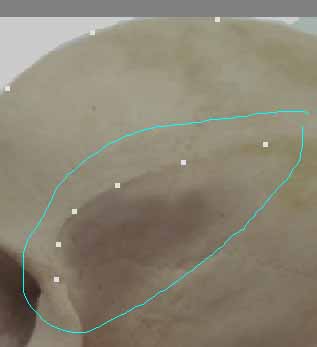 I press the 't' key to enter the 'Move' mode and pointing to the 'Back' viewport click and drag the points to the right. I press CTRL-t to enter the 'Drag' mode and drag each dot to line up with the same contour line. I try not moving the dots up or down at all as I drag them.  I will place four sets of six dots between those two rows. I judge 1/5 of the way between the two rows, and in the 'Back' viewport I lay 6 more dots using the '+' (Add Points) tool. I press CTRL-t to enter the 'Drag' mode and in the 'Right' viewport drag them straight to the left until they feel like they'd be laying along that contour. 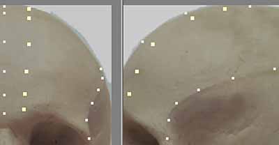 I lay all four sets of contour lines between the two lines. Afterwards, I make sure all points are de-selected by pressing spacebar if I'm currently in a tool, and '/' to deselect all. I press CTRL-t to drag the points and I drag them into finer contours until they all feel correctly spaced. Remember that as things get more steep, the points will lie closer together.  I go to the 'Perspective' viewport and select 'Wireframe' as the view type. I rotate the view by pressing ALT and click-draging until I can see the entire forehead, I enter the point mode by pressing CTRL-g, selecting each set of four points comprising each four-sided polygon clockwise... 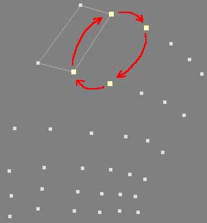 I press 'p' to set the polygon. I do the next, and the next, and the next until all forehead polygons have been laid down. Once I'm done, I change to the 'Shaded Wireframe' view type and press CTRL-h to enter polygon mode. I select each polygon which isn't gray, pressing 'f' to flip those so they are all faces are pointing outward. I press the TAB key to see what the surface looks like in SubSurfacing mode and rotate the 'Perspective' viewport to see if it looks correct. 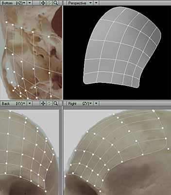 I press TAB to exit SubSurface mode. Next, I do the side of the head in the same manner. I press '+' key on the keyboard to enter 'Points' mode, laying six more dots continuing the contour down the side of the head. I press 't' to enter the 'Move' mode and in the 'Back' viewport move the line of dots to the right to line up the top dot properly. I enter CTRL-t to drag the individual points, dragging sideways in the 'Back' viewport making sure I don't go up or down. Once the second set of points is laid down, in the 'Back' viewport the points will be so close together that I'm not be able to see the separate points any more.  This makes it difficult to drag individual points. When this occurs, I highlight just that one point in the 'Right' view, and when I enter CTRL-t (Drag) mode, it will only be able to drag the highlit one. This trick can be used in the middle of an intricate mesh whenever you have lost the abilty of keeping track of individual points that are lined up in a line, also. When I hightlight just one point, I have to exit from the tool mode by pressing the spacebar, clicking on the old highlit point and it de-selects, I click the new point to select it, I re-enter drag mode by pressing CTRL-t, dragging that next point in the 'Back' viewport until all six have been arranged. I return to the 'Perspective' window after laying two lines, choose 'Wireframe' view type, start selecting each polygon in a clockwise (or counter-clockwise) manner pressing 'p' to create each polygon after the fourth point has been selected. 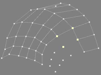 I re-enter 'Wireframe Shade' view type, highlight any polygons which may be backwards and press 'f'. Unhighlight all polygons and press the TAB key to see how it looks. I can always press CTRL-t to drag any point in the 'Perspective' viewport to correct a contour. I hold down ALT, click-hold-and-drag the left mouse button to view all angles. I enter the 'Smooth Shade' view type to give a closer idea of what it would look like, rendered. 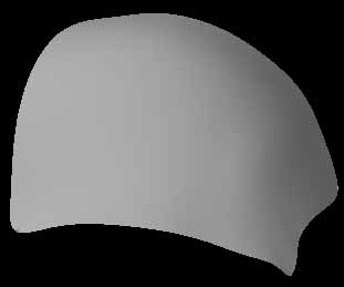 I press TAB to exit Subsurfacing mode. This method of doing a little at a time is a powerful one. It is far easier to control than if you tried creating the whole head at once. Also, it is best to do sections that are most important first, then worry about how you will join the pieces afterward. That way, the detail is preserved and the bad places where puckers might occur will happen at juncture lines, which makes sense and feels right. I lay down the next row, thinking of the contours as they would pass UNDERNEATH the eyesocket bridge. I notice that the selected point is not on the zero X axis, so I highlight it... 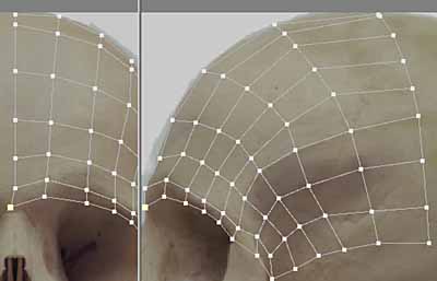 I press 'i' to bring up the 'Point Info' panel.  I change the X value for that point to zero, and click 'OK'. Before I saw that this point was not on the zero axis, I noticed a strange thing happening. That square seems to be a triangle, not a four-sided polygon... 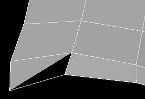 ... yet when I do a 'Construct' tab, 'Rem Polygons' (the 'k' key), highlighting the four points again, press 'p' to remake the polygon - the same thing occurs. When I press the TAB key to enter the SubSurface mode, it says:  So, something I did caused polgons to appear which have less than four points. I press TAB to turn off subsurfacing mode again. I enter the Polygon mode by pressing CTRL-h, make sure all polygons are de-selected, selecting all polygons by clicking with my right mouse button and dragging a cyan circle around the object. I zoom the 'Back' viewport so I'll be able to see the polygon number of that polygon, pressing the 'i' key to bring up 'Polygon Info' panel. I drag it's scroll gadget down until I can see #46 and #47 and find that they both somehow have 5 points, not four. 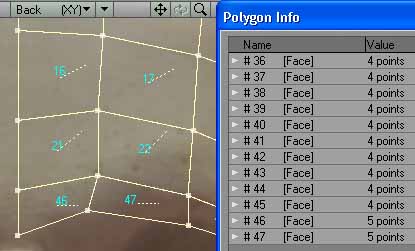 I click on #45, move up to #1 and 'SHIFT/left-click' it. I click  This will only leave the two offending polygons selected.  I press DELETE to get rid of them. I redraw those two missing points, position them again, ensure that the one that is on the zero X axis is numerically zero, redo the polygons by selecting points in a clockwise direction, pressing 'p'. The eye socket bridge will be extended from these four points, later. Note how I positioned them as if they encircle the four corners of an invisible tube which will grow from that point. Four points aren't really enough, so I'll probably add a couple points to that square before I extend it.  I save the skull as 'SkullTutorial1.lwo'. This page is growing rather long, so on to the next page... Click for a Rotating 3D Version of the skull done using the Blaxxun3D Applet |
||
