
|
|
||
|
24. A Human Skull - Image Preparation 2 |
||
 SCALING THE IMAGES TO CREATE A BOX IN MODELER In order to have Modeler know what shape to place the images into, you must first create a head-sized box. The box will just be used by Modeler to determine how big the images should be that are placed which will let us create the object. That box must have the exact same ratios that the images that you made have. SCALING THE 'FRONT' SKULL IMAGE I bring the front.bmp image into Photoshop. I right-click on the eyedropper tool in Photoshop's Toolbar and select the Measurement Tool (or press the 'i' key).  I point the tool at the widest part of the left side of the face and click the left mouse button. A small cross appears. I hold the SHIFT key down, move the mouse to the right and click on the rightmost cheek.  Looking just below the menus where it says W: and H:, I can now tell how wide it is between the cheekbones in this image.  From this, I can tell that it is W = 8.229 inches between the cheekbones. So, the image of the head is bigger than an actual person's head would be. However, in LightWave, the default is metric in either millimeters or meters. Millimeters are more accurate, so lets go with millimeters for converting. In Photoshop I choose 'Edit->Preferences->Units & Rulers'  If you chose any tool at any time so the measurement tool goes away, you can get back the last measurement without having to measure it again by right clicking the eyedropper icon again and selecting the 'Measurement Tool' again. The line will reappear. The value is now in millimeters.  It says the width between image cheekbones is 209 mm. "Oh oh..." You're probably saying, "I smell more math coming..." MEASURING YOUR HEAD You will use one real measurement from your own head along with the pixel sizes of the files to determine the size the box should be. It doesn't have to be perfect, but take a ruler, look in the mirror, and lay the ruler in front of your face so you can see the markings in the mirror and decide what the widest width of your cheekbones is to the nearest 1/4". There's a bit of parallax error in my mirror, but by tipping my head left to right I guess that it's 6 inches from cheekbone to cheekbone. There are 25.4 millimeters in 1 inch. Therefore there are 152.4 mm in 6 inches. The Lightwave box will be the same size as my head. Therefore, the width of box cheekbones also = 152.4 mm. From that, I can figure the entire box's dimensions. In Photoshop I do 'Image->Image Size' on the 'front.bmp' image.  The width of image head is 224.37 mm wide. The height of image head is 356.31 mm wide. The depth of the image head can be gotten from the width of the right.bmp image so I load it into Photoshop. I do an 'Image->Image Size...' and look at the 'Document Size: Width'.  The depth of image head is 369.36 mm wide. Here are the Image Head Dimensions: width of image = 224.37 mmKNOWN: width of image cheekbone = 209 mmThus, if I multiply the three numbers above by the reduction factor of .73, that will be a good size for the box. The reduced sizes for width, height and depth arrange in the order I'll be entering them in LightWave's Box Tool Numeric requester LightWave box dimensions: width of box = 163.6 mmMODELER, CREATING THE BOX Open the Modeler program. From the 'Create' tab, 'Objects' section, select 'Box' or press SHIFT-X.  Press the 'n' key to bring up the numeric panel. Enter the values for width, height and depth. Enter the value 0 m for the Center's X, Y and Z coordinates.  The box will be created. It will look very long and thin when you turn it in perspective mode, but remember that the forehead slopes backwards. Only the tip of the nosepiece and back of the head will touch the box.  Press the 'ENTER' key to set the box. Enter 'Polygon' mode by pressing CTRL-h and select all of the box's polygons. In the 'Back' viewport click the right mouse button and draw a cyan circle around the box to select all polygons.  MODELER, DEFINING VIEWPORT BACKDROP IMAGES In the 'Top' viewport, set it to 'Bottom' instead.  Press 'd' key to bring up the 'Display Options' panel and choose the 'Backdrop' tab.  MODELER, BACKDROP FOR TOP LEFT VIEWPORT It should already be on TL (Top Left Viewport). We will put the image for 'Bottom' there. Under the 'Image' dropdown, select 'Load' and pick the 'bottom.bmp' image that you did. It will the wrong size. Click on 'Automatic Size'  ... and it will fit inside the box's dimension. Set the image resolution to the best resolution (1024).  MODELER, BACKDROP FOR BOTTOM LEFT VIEWPORT Click on the BL button (Bottom Left) and load the 'front.bmp' image, again doing an 'Auto Size' afterwards. Set the image resolution to the best resolution (1024). MODELER, BACKDROP FOR BOTTOM RIGHT VIEWPORT Click on the BR button (Bottom Right) and load the 'right.bmp' image, again doing an 'Auto Size' afterward. Set the image resolution to the best resolution (1024). Now, you should be able to see the skull image in each pertinent viewport.  Unfortunatetly, the images won't stay there when you save your object and exit Modeler. The next time you load the object, the backdrop images will be gone. However, if you do one thing you can save yourself a lot of time the next time you load the object and wish to keep working using the backdrop images. Press 'd' to bring back up the 'Display Options' panel if you closed it and again choose the Backdrop tab. Under the  drop-down... drop-down...Select 'Save All Backdrops'.  Give it a name and save it. It will add .cfg to the name you save. Next time you want those backdrops in those windows, load that preset with a 'Presets->Load Backdrop'. MODELER, PROPERLY ORIENTING THE IMAGES Now is the time to decide if things are oriented correctly. If you have forgotten what is 'forward', 'backward' and so-on then review in Tutorial #2 - 'Getting Started' There, you will see that in the 'Top' (or 'Bottom') viewport, the top of the viewport is the 'front' of the world. However, I always turn my objects around in the world so the back is the front. Therefore, the 'bottom.bmp' image is upside-down. I will go return to Photoshop, I will do an 'Edit->Transform->Flip Vertical' and resave it, flipping the picture so the teeth point downward. Since the jaw is symetrical, I don't have to worry about whether to flip it or rotate it. To get LightWave to rethink the picture, I enter the Image Editor' by pressing F4. I click on the name 'bottom.bmp' in the 'Name' section to the left. I click on 'Replace' button, finding that file again and it will refresh. Finally, in the 'Right' viewport, that image is also pointing in the wrong direction. The nose is pointing to the 'front of the world'. It needs to be pointing towards the left, or 'back of the world'. I bring the image into Photoshop and flip it horizontally with 'Edit->Transform->Flip Horizontal'. In LightWave, I 'Replace' the image from inside the 'Image Editor' (F4) as I did with the bottom image. The backdrop images look nice and fresh, and clear... They're perfect, right? Well, not exactly. When you draw points, both the points and polygon lines will be drawn in white. You won't be able to see the lines or points the way the backdrop images currently are. Again bring up the 'Display Options' panel by pressing the 'd' key and click on the 'Backdrop' tab. Drag both the brightness and contrast slider knobs to the left.  The picture won't be nice and pretty any more, but you'll be able to see the points when you lay them down. If you still can't see points when you place them, drag the sliders even more to the left. 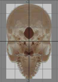 Do this for all three viewports.  Any time you make a change in the Backdrops, make sure you remember to again do a 'Presets->Save All Backdrops' and overwrite the old preset with the same name. You should do this even if you're not sure the change actually constituted a real difference in the preset.  MODELER, SAVE SEPARATE OBJECT JUST AS THE BOX Realize that the box can cause you problems. It was put there JUST TO SIZE THE IMAGES, and now it is useless to you unless the backdrop preset disappears. It is easy to forget all about the box. If you were to forget the box were there, they you were to start rendering the skull, the box might block light from landing on the skull and you wouldn't know why that was happening. Therefore, I recommend that you make two copies. Save one copy called 'SkullBox.lwo'. Do it now before you forget... then, don't touch it. Call the second one 'skull.lwo' and have it be the one you draw in. You are now ready to start creating the skull. Click for a Rotating 3D Version of the skull done using the Blaxxun3D Applet |
||
