
Here are a few pics of my landing gear assemblies. These are modeled after a design by Chris Walterson, Steve Laribee, and Pat Panzera, which I decided to use instead of the composite LG legs I already have. What you see below constitutes about a whole day of work! (1/4" 4130 is tough stuff!)
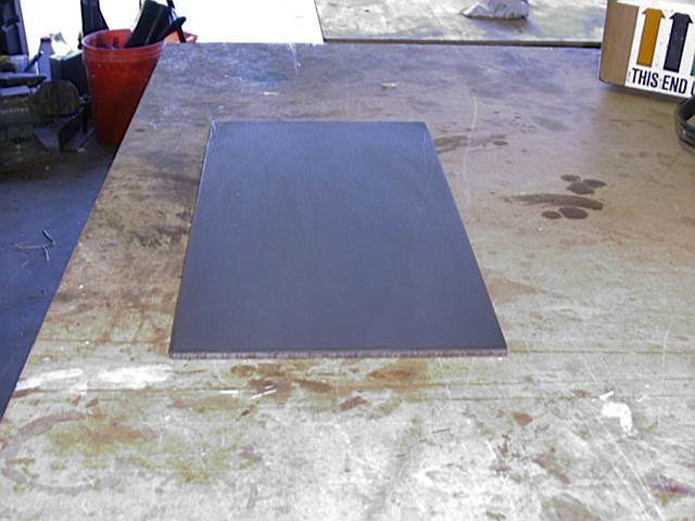 The LG yokes will be
made from this one
sheet of .25 4130. The
grain is along the long axis.
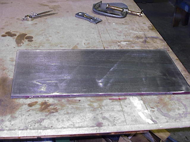 Here is what it looks like after the
initial cleaning.
Here is what it looks like after the
initial cleaning.
Before I painted on the layout dye, I belt sanded the sheet of steel with my 4x21" sander, with 60 grit paper. This was done to clean off a lot of the rough texture that is left behind from the hot rolling process. After all of the individual pieces were cut from the flat stock, I again belt sanded them with an 80 grit belt.
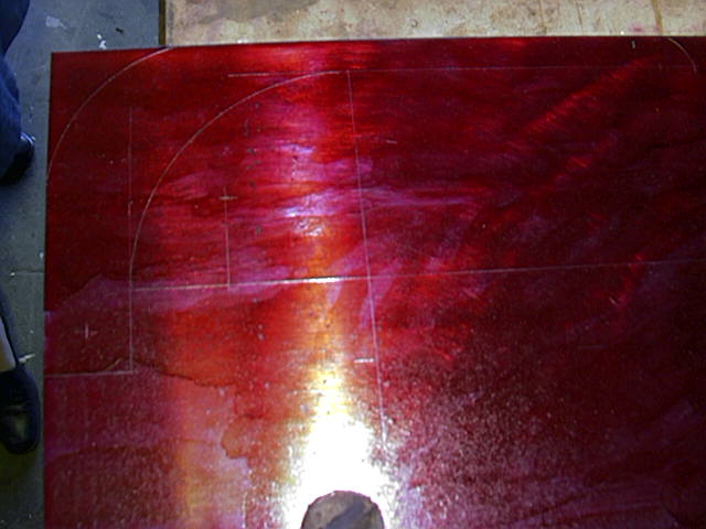 If you look closely, you can see the
layout lines. Yes, I know I went a little overboard w/ the layout dye, but I got
caught in the moment!
If you look closely, you can see the
layout lines. Yes, I know I went a little overboard w/ the layout dye, but I got
caught in the moment!
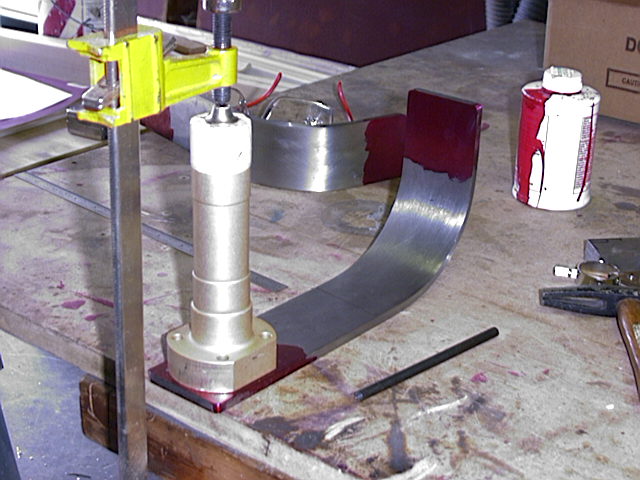
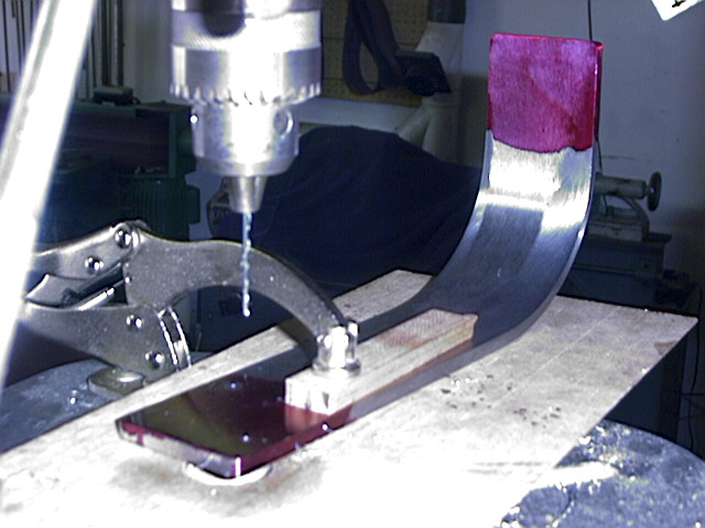
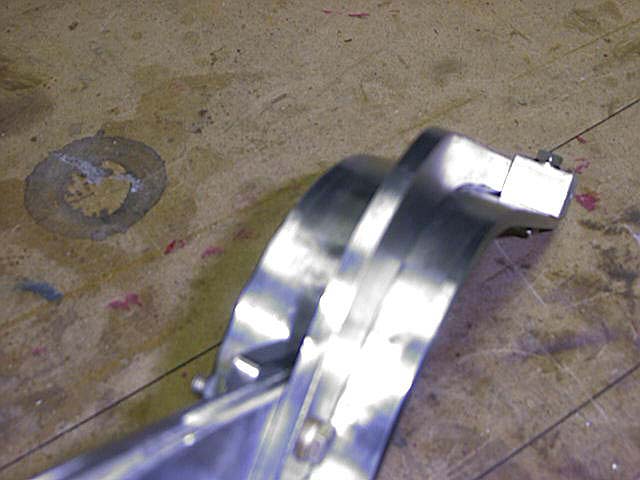
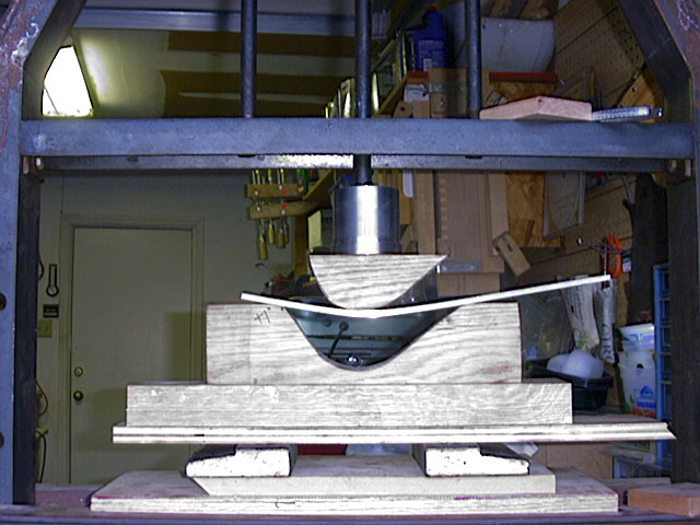 Here is one of the legs being formed
in my megabuck press. The form is from white oak, and the curves look a little
wrong, but I had to account for springback. This took about a minute to press
into shape.
Here is one of the legs being formed
in my megabuck press. The form is from white oak, and the curves look a little
wrong, but I had to account for springback. This took about a minute to press
into shape.
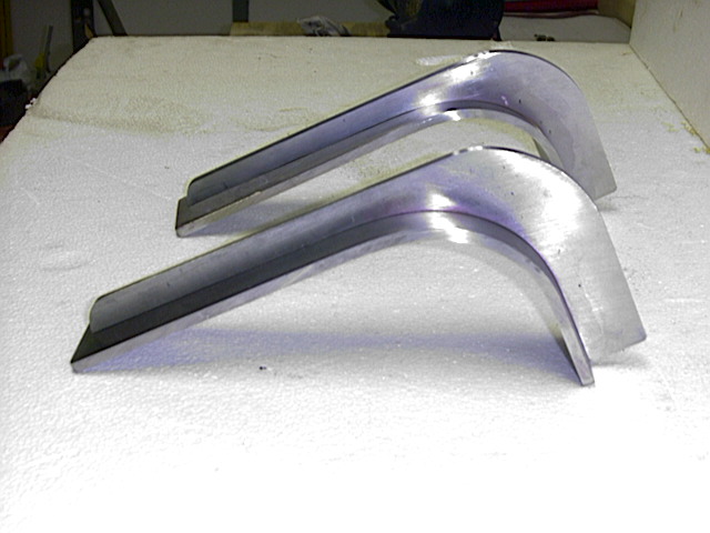
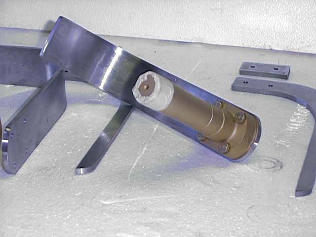
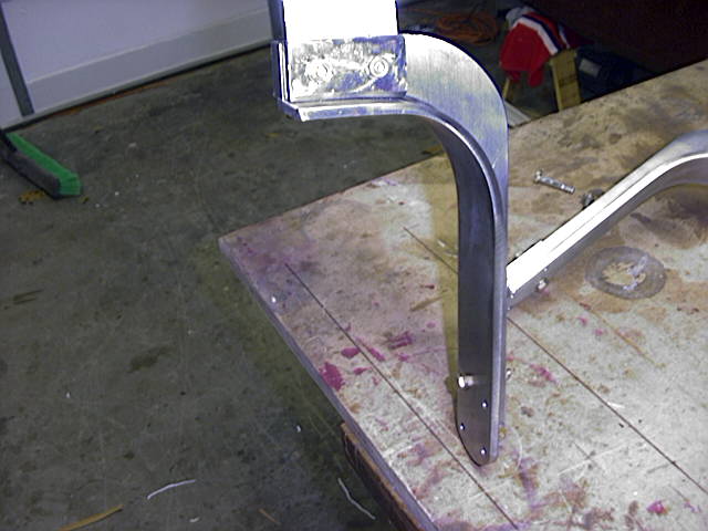
 A picture of the assembly a little
farther along. Tomorrow I'll drill holes to mount the axles and the actual
spring steel leg. I also have to fabricate the back plates.
A picture of the assembly a little
farther along. Tomorrow I'll drill holes to mount the axles and the actual
spring steel leg. I also have to fabricate the back plates.
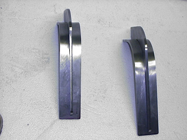
 Side view of the same
thing.
Side view of the same
thing.
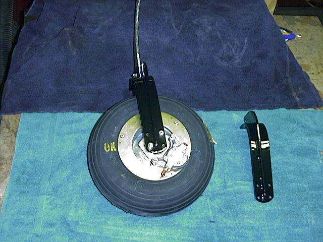
 Here I am marking the position of
the axle mount bolt holes. If you look closely at the little black punch (on the
bench, beside the leg) you can see that it is actually a 1/4" transfer punch.
Makes precisely centered punch marks.
Here I am marking the position of
the axle mount bolt holes. If you look closely at the little black punch (on the
bench, beside the leg) you can see that it is actually a 1/4" transfer punch.
Makes precisely centered punch marks.
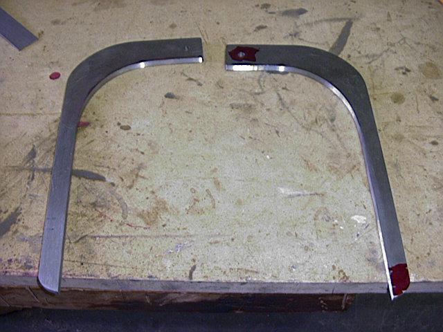 A view of the side supports with the
first of the leg mount holes drilled.
A view of the side supports with the
first of the leg mount holes drilled.
 Drilling the axle bolt holes.
Started with a sub-microscopic drill, and stepped it up 3 times before I drilled
the hole to final size.
Drilling the axle bolt holes.
Started with a sub-microscopic drill, and stepped it up 3 times before I drilled
the hole to final size.
It's extremely important to go slow, and ensure your drill bit is exactly centered.
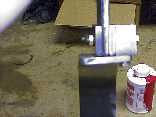
 A shot of the axles bolted into
place for the first time. The mount holes came out perfect! Here I am preparing
to scribe the outline of the axle on the leg, for final trimming.
A shot of the axles bolted into
place for the first time. The mount holes came out perfect! Here I am preparing
to scribe the outline of the axle on the leg, for final trimming.
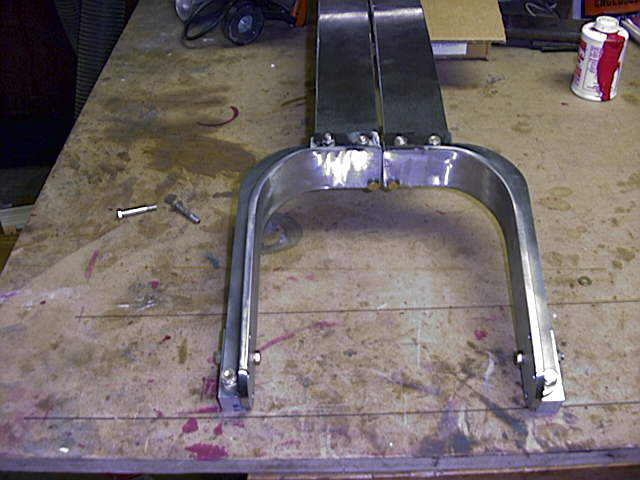
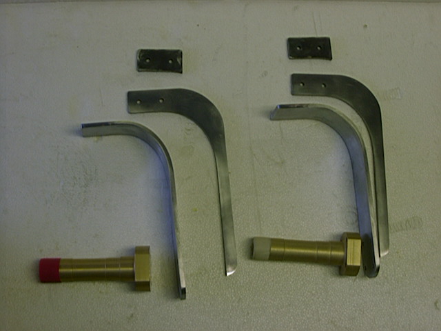 Here are all of the key pieces to
the yoke assembly. Next, I have to chamfer the edges of the side reinforcements
where the will be welded to the leg. Almost ready to go to the
welder.
Here are all of the key pieces to
the yoke assembly. Next, I have to chamfer the edges of the side reinforcements
where the will be welded to the leg. Almost ready to go to the
welder.
 Just about
ready for the welder. In this photo, the chamfering still has to be
done.
Just about
ready for the welder. In this photo, the chamfering still has to be
done.
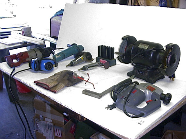 Here are some of the tools it took
to get to this point:
Here are some of the tools it took
to get to this point:
Sawzall, jigsaw, grinder, angle head air grinder, high speed cutoff tool, bench grinder, transfer punches, 4 inch grinder, drill press, wide belt edge sander, hydraulic press, various layout tools. It seems that even the small projects require most of the tools in the shop!
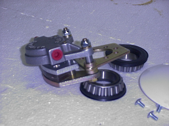
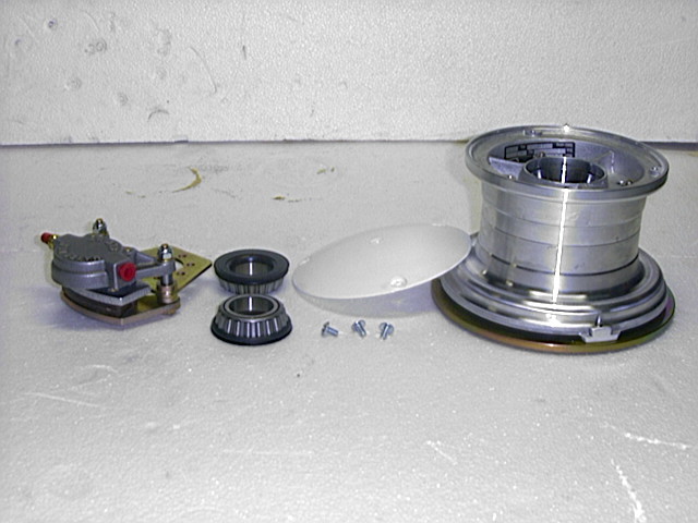 Here are the Matco 5" wheels and brakes. What you get when you order
them is 2 of everything you see here. 4 wheel bearings, 2 calipers, 2 brake
discs, 2 little hub caps, and 2 complete wheels. What you don't get are axles,
spacers, washers, and axle nuts. Make sure (if you order these wheel and brake
assemblies) that you get the 7/16" spacers that are required to locate the
wheels at the proper position on the axles. As it stands, I'm gonna turn my own
on my lathe.
Here are the Matco 5" wheels and brakes. What you get when you order
them is 2 of everything you see here. 4 wheel bearings, 2 calipers, 2 brake
discs, 2 little hub caps, and 2 complete wheels. What you don't get are axles,
spacers, washers, and axle nuts. Make sure (if you order these wheel and brake
assemblies) that you get the 7/16" spacers that are required to locate the
wheels at the proper position on the axles. As it stands, I'm gonna turn my own
on my lathe.
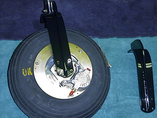
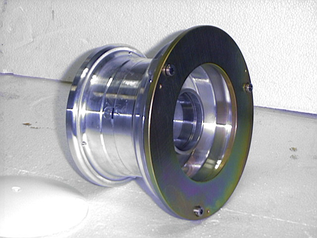 This is how the brake disc mounts to
the wheel. It is actually installed onto the wheel after the wheel is placed
onto the axle. The wheel uses 2 timken roller bearings.
This is how the brake disc mounts to
the wheel. It is actually installed onto the wheel after the wheel is placed
onto the axle. The wheel uses 2 timken roller bearings.
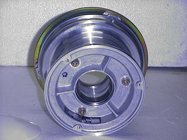 The other side of the wheel. Visible
are the bearing race and screw holes for the hub cap.
The other side of the wheel. Visible
are the bearing race and screw holes for the hub cap.
 Here is one of the calipers. On this
end is the inlet port for the brake line. On the opposite side is the bleeder
port.
Here is one of the calipers. On this
end is the inlet port for the brake line. On the opposite side is the bleeder
port.
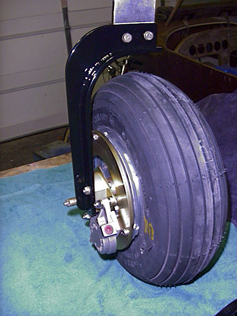
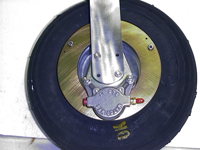 The assembly temp installed. The
caliper will get rotated about 30 degrees one way or the other (depending on
what side of the airplane it goes to)
The assembly temp installed. The
caliper will get rotated about 30 degrees one way or the other (depending on
what side of the airplane it goes to)
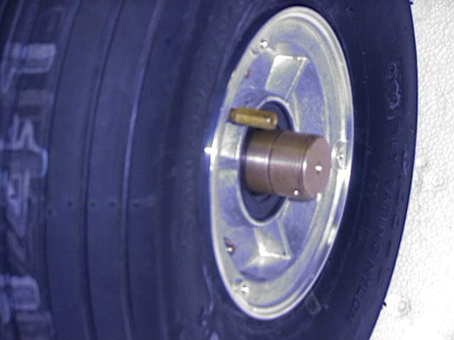 Here you can see why the spacers are
required. The wheel assembly is too far inboard by about 7/16". The caliper is
also binding.
Here you can see why the spacers are
required. The wheel assembly is too far inboard by about 7/16". The caliper is
also binding.
This is how the legs look now. I jigged the pieces together using drilled and bolted aluminum blocks.
 If you look closely, you can see the
chamfer that is ground on the support piece.
If you look closely, you can see the
chamfer that is ground on the support piece.
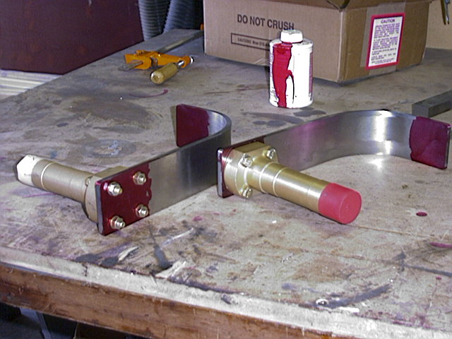
 Here are both legs assemblies, ready
for the welder.
Here are both legs assemblies, ready
for the welder.
Here you can see the chamfer on the backing plate. This is ground at 45 degrees, with approx. a 1/16" space to complete the head weld. This should allow 100% strength.
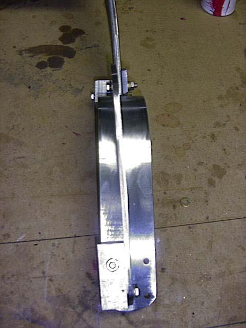
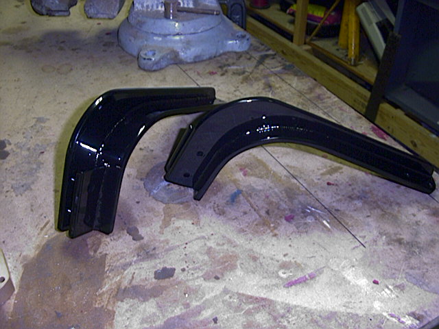
Well, Folks, it's the 18th of December, and I just got the legs back from the welder. Below are a few pics of how they turned out.
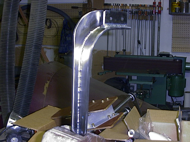
The welds are very even, with penetration obvious through the thickness. I am very pleased with the end product.
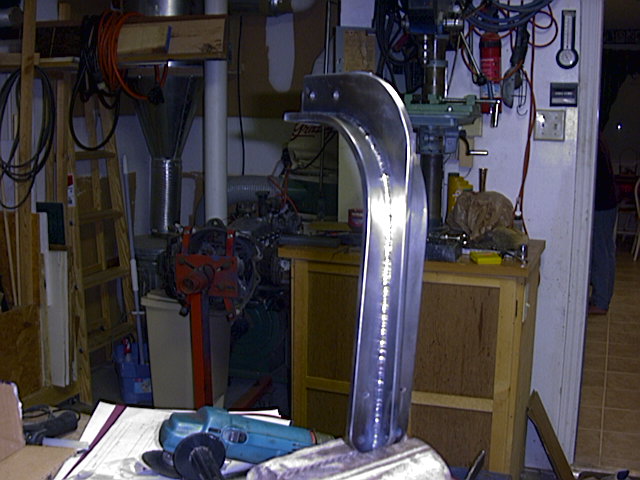 Here's another view of the same
piece.
Here's another view of the same
piece.
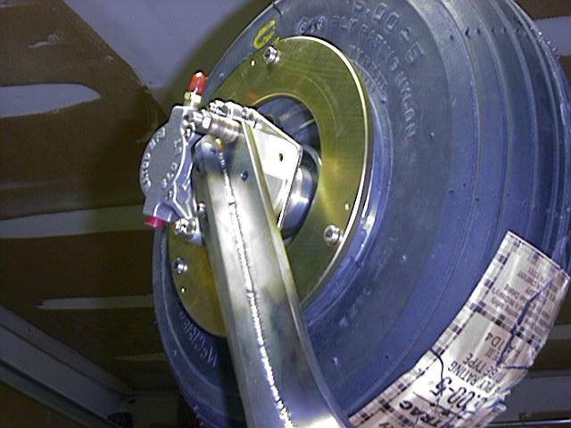
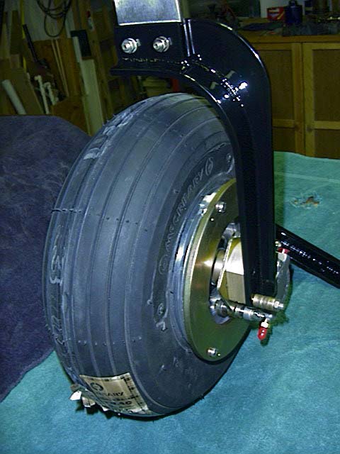
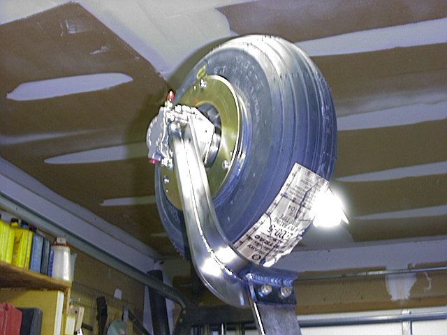 Here you can see the almost
completed assembly. I turned the spacers to properly locate the wheel assembly
on the axle, so the brakes work right, now.
Here you can see the almost
completed assembly. I turned the spacers to properly locate the wheel assembly
on the axle, so the brakes work right, now.
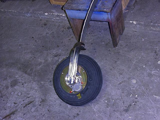
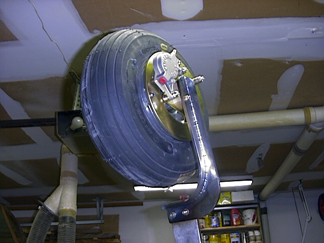 Yet another view of the same
thing.
Yet another view of the same
thing.
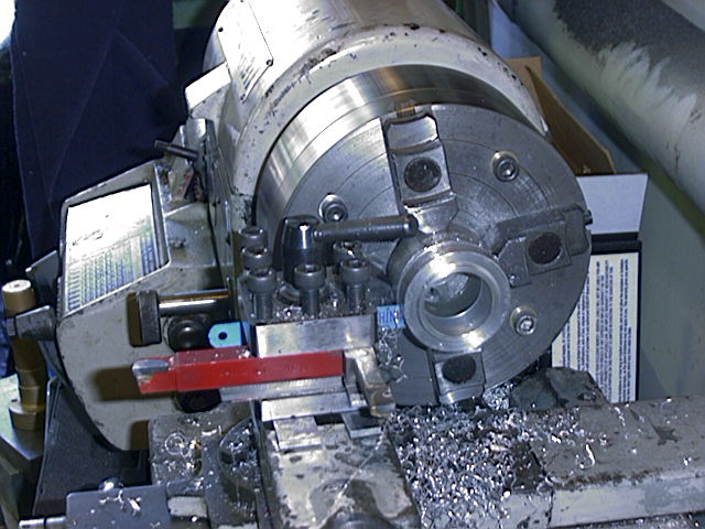
Here is one of the special spacers I had to make in order to properly position the wheel on the axle. The chamfer on the face of it is made to press against the bearing race, while the larger face of the spacer will contact the bearing seal.
Here you can better see the spacer I had to make on my lathe to properly position the wheels on the axles. There is another special washer on the outboard side.
Here is the near-completed assembly. I may stress relieve the yoke, depending on the feedback I get this weekend, but either way, they are off to be powder coated on monday.
Monday, 20 December
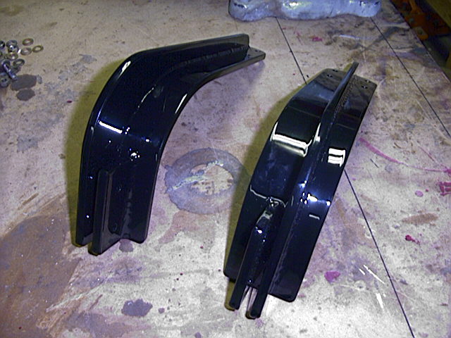
The powdercoating turned out fantastic. I dropped them off at 12, and picked them up at 4:30... the same day!
This gives a better idea of how purty the powdercoat came out!
Well Folks, that's the last of the landing gear page. Later, I'll fold this into a seperate area where the whole landing gear and gear box assembly is put together.

