
Figure 4B.1 Oscilloscope Photo
Showing Effect of Secondary Emission.
Scales, X = 20 V/cm, Y = 2 mA/cm.
Grid voltage = 0.5 volts per step,
EC = 0 at the top. EC2 = 100 V.
For a verbal description click here.
Chapter 4B Multi Grid Tubes.
4B.1 Odes to Tetra and Penta.
4B.2 The Heptode, Pentagrid Converter.
4B.3 The Beam Deflection tube.
4B.4 Magic Eye and Cathode Ray Tubes.
4B.5 Oscillators.
4B.6 Problems.
4B.7 Answers to Problems.
Chapter 4B.
Multi Grid Tubes.
Development of the vacuum tube moved rapidly after the first triode was set loose on the world. The tetrode, pentode, and heptode had all been developed by 1930. Although they were considerably refined over the following 30 years the changes consisted mainly of the way in which they were packaged. The only significant development of which the writer is aware is the beam deflection tube which came out in the late 1950s, but we are getting ahead of ourselves.Back to Fun with Transistors.
Back to Fun with Tubes."
Back to Table of Contents.
Back to top.
4B.1 Odes to tetra and penta.
The triode was, and is, a pretty good tube but it does have a few problems. These problems were curable by inserting more grids into the tube. This gave rise to the Tetrode, 4 element tube, and the Pentode, 5 element tube.Problems with the Triode.
The misbehavior of the Triode was attributed to the effect of plate to grid capacitance. There were two basic problems. These were 1) the miller effect and 2) oscillation. Due to the way a tube is constructed there is capacitance between the plate and grid. Because the tube inverts the signal the capacitance appears to be much bigger than it actually is. We studied the Miller effect in the previous chapter. If you don't remember that, it is suggested that you review section 4A.5.Oscillation.
When triodes are used as radio frequency RF amplifiers all Hell breaks loose. The phase shifts that result from the use of tuned circuits in the grid and plate cause the signal fed back through the plate to grid capacitance to be positive feedback. That spells oscillator. If that's what you wanted then your delighted. But if you wanted to amplify small signals to make them bigger you would not be a happy camper.There is such a thing as neutralization where in the circuit is arranged to feed signal back to the grid which is always opposite in phase and equal in amplitude to that fed back through the plate to grid capacitance. Neutralization is hard to adjust and increases circuit complexity. If there was only a way to reduce the plate to grid capacitance...
The Tetrode.
The logical thing to do seemed to be to place an additional grid between the control grid and plate. This grid could be placed at AC ground potential and would act as an electrostatic shield between plate and grid. Also the screen grid, as it was called, could be placed at a positive potential which would increase the gain of the tube by pulling more electrons toward the plate. However, a serious problem set in.Secondary Emission.
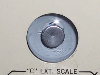
When electrons strike the plate they are carrying a lot of kinetic energy. They give up that energy, in the form of heat, to the plate. The plate gets hot enough to begin emitting electrons. The impact of the incoming electrons helps to liberate others from the plate material. Think of them as being knocked loose. In a triode these secondary electrons have no place to go except back to the plate. It is the most positive thing in sight. In a pentode the screen grid is sitting there at a positive potential and because the plate voltage is going up and down with signal the screen grid may be, at that instant, more positive than the plate. The secondary electrons take off for the screen grid and ignore the plate. This takes away from plate current and adds to screen current. Both things are bad. But even worse is the negative resistance effect. There is a point where an increase in plate voltage will give a decrease in plate current. If you try to work that one out with ohm's law you get a negative value for resistance. This phenomenon is shown in the oscilloscope photo below.
Figure 4B.1 Oscilloscope Photo
Showing Effect of Secondary Emission.
Scales, X = 20 V/cm, Y = 2 mA/cm.
Grid voltage = 0.5 volts per step,
EC = 0 at the top. EC2 = 100 V.
For a verbal description click here.
Note the area where the line slopes slightly down to the right. This effect can be, and has been, used to make an oscillator but in an amplifier it leads to massive distortion. That's why there aren't any true tetrodes in your tube manual, unless you have a very old one.So if there aren't any true tetrodes, how did I get these curves. I used a modern tube and tied the suppressor grid to the plate. Just as tying the screen grid to the plate makes a triode, tying the suppressor grid to the plate makes a tetrode. Even with that, modern materials used in tubes don't allow very much secondary emission. The effect would be much more pronounced if an older tube were used. This was a 6AU6. The curves for a properly connected 6AU6 will be seen below.There were two basic solutions to the problem of secondary emission. One was to add yet another grid making a pentode, and the other was to cause the electrons to bunch up making a space charge that would repel secondary electrons back to the plate.The beam Tetrode.
I can't say which came first historically speaking. Both solutions seem to have been around a long time. I have seen tubes such as the 6L6 called beam tetrodes in an old Tung-Sol manual I used to have. In looking through a 1937 RCA manual I find the 6L6 referred to as a beam power amplifier although the diagram shows only two grids and two little angled lines between screen and plate but positioned on either side.I did find a 22 which is called a "SCREEN-GRID RADIO-FREQUENCY AMPLIFIER". The specified screen voltage is less than 1/2 of the plate voltage. With the screen voltage set so low the excursions of plate voltage in an RF amplifier would not be large enough to take it into the secondary emission area.
The word "tetrode" must have already become a "4 letter word" among electrical engineers and had been banished from RCA literature by 1937.
Beam tetrodes operate by having the control grid and screen grid wires very accurately aligned. This minimizes electron collisions with the screen and causes the electrons leaving the screen to travel in thin beams. The plate is a little farther from the screen grid than it would otherwise be and there are two vertical pieces of metal that are internally connected to the cathode. These compress the electrons into a horizontal beam and form a concentration of negative charge that works to repel secondary electrons.
This structure can be clearly seen in a 6CB6. The grey rectangular plates are where the electrons impact. The silver colored pieces are the beam forming electrodes. The screen and plate are seen surrounding the cathode. The semicircular band is to support the two halves of the plate and connect them electrically. A picture I take can't do it justice. You need to hold one of these tubes in your hand and turn it at different angles to see how it is made. Although the tube manual calls this tube a pentode and the diagram shows a suppressor grid it is not brought out to its own pin as true suppressor grids are.
If you decide to break a tube and disassemble its innards, be careful. First of all, don't cut yourself on the broken glass. However there is a more subtle danger. Most of the materials used in tubes are rather toxic. I would urge you to handle them with gloves and when you are finished wrap them in several layers of aluminum foil before throwing them away. The contents of one tube thrown away isn't going to constitute a hazardous material spill but thousands would.
The True Pentode.
The pentode is constructed by inserting a third grid between the screen grid and plate. So now there are three grids in our tube. You may think it's getting a little crowded in there but just wait until we get to the heptode. The third grid is called the suppressor grid or usually just the suppressor. It is usually placed at the same potential as the cathode. In some tubes it is internally connected to the cathode although these may be beam tetrodes. The wires of the suppressor are widely spaced as compared to the control and screen grids so there is little effect on the high energy electrons coming from the cathode on their way to the plate. The secondary electrons are much lower energy and the suppressor is just enough to discourage them from going anywhere but back to the plate. In some special applications the suppressor grid may be used to control the gain of the amplifier tube. This can turn the pentode into a voltage controlled amplifier (VCA).So there we have the modern pentode tube. High gain, small Miller Effect, and low likelihood of oscillating. As you might have guessed by the tetrode characteristics above the pentode characteristics are nothing like those of the triode. Figure 4B.2 shows the plate curves for a 6AU6 taken with a curve tracer and oscilloscope.
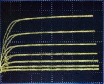
Figure 4B.2 Oscilloscope Photo
Showing Characteristic curves for a 6AU6.
Scales, X = 20 V/cm, Y = 2 mA/cm.
Grid voltage = 0.5 volts per step,
EC = 0 at the top. EC2 = 100 V.
For a verbal description click here.
The tangle of lines at the left is an artifact of the curve tracer. If the plate voltage sweep is turned down they untangle and appear as they should. The almost horizontal lines mean that the plate resistance is very high and the best model for a pentode is a current source. Note that, unlike the tetrode, there is no change in the plate characteristics even when the plate voltage drops below the screen voltage.Practical Circuit.
Like the triode the pentode can be connected as a resistance coupled amplifier. The tube manual circuit is shown below.

Figure 4B.3 A Pentode Resistance Coupled Amplifier Stage.
For a verbal description click here.
Once again the heater connections are assumed. The notation used here is consistent with the resistance coupled amplifier charts found in all tube manuals. You can design a pentode amplifier based on these charts, they will give you the gain and distortion at two values of input voltage.In the next subsection you will see that small signal calculations are not accurate enough to be useful. However they can be used to correct the gain figures from the charts for an unbypassed cathode resistor.
Small Signal Calculations.
The equivalent circuit and calculations are quite different from the triode amplifier. The circuit is shown in Figure 3 below.
Figure 4B.4 The Small Signal Circuit of a Pentode.
For a verbal description click here.
When you look up a pentode in a tube manual you will find the transconductance rather than the amplification factor. If you are curious you can calculate it very simply. The amplification factor of a pentode may be found by,μ = Gm rp (4B.1) Where μ is the amplification factor, Gm is the transconductance in mhos and rp is the plate resistance in ohms. The transconductance is always stated in micro mhos. The gain of a pentode amplifier may be calculated by,Av = Gm rp Rbc / ( rp + Rbc) (4B.2) Where Rbc is the parallel combination of Rb and Rcf as follows.Rbc = Rb Rcf / (Rb + Rcf) (4B.3) Where Gm is the transconductance of the tube, rp is the plate resistance, and Rbc is the parallel combination of Rb and Rcf as defined in equation 4B.3. The derivation of equation 4b.2 is so similar to that for the triode that it will not be given here.One note of caution. The transconductance of a pentode is very sensitive to screen grid voltage. For example, for the 6AU6 the lowest value for transconductance is given for a screen voltage of 100 volts. Yet the resistance coupled amplifier charts give values of Eg2 of around 40 volts. Obviously the value of Gm needs to be scaled down accordingly. The tube manual gives a graph of transconductance versus grid number 1 voltage for values of grid number 2 voltage of 50, 100, and 150 volts for the 6AU6. An example will illustrate.
Example 4B.1
A 6AU6 has a stated transconductance of 3900 micro mhos and a plate resistance of 0.5 meg ohms. Calculate the gain for a plate resistor of 270 k ohms and a following stage grid resistor of 470 k ohms.Solution:
First calculating the value of RbcHere is the data from the resistance coupled amplifier chart for the 6AU6.Rbc = 270 k x 470 k / (270 k + 470 k) = 171 k ohms.
Av = Gm rp Rbc / (rp + Rbc)
Av = 3900 micro mhos x 500 k x 171 k / (500 k + 171 k) = 497
So which one is right? The chart of course. It was based on actual measurements performed in the laboratory.
Ebb = 250 volts.
Rb = 270 k ohms.
Rc2 = 680 k ohms.
Rcf = 470 k ohms.
Rk = 1,000 ohms.
Ic2 = 0.30 mA.
Ib = 0.74 mA.
Ec1 = -1.0 volt.
Ec2 = 40 volts.
Eb = 50 volts.
Esig = 0.1 volt AC.
Eout = 25 volts AC.
Gain = 250.
% Dist = 1.1 %.
Esig(1) = 0.22 volts AC.
Eout = 47.7 volts AC
Gain = 217.
% Dist = 2.6 %.
(1) Taken at the point of 1/8 microamp of grid current.We do have curves for the 6AU6 of transconductance versus grid 1 voltage for three values of screen grid voltage including 50 volts. 50 volts is close to 40 volts and we are given the grid 1 voltage. Looking at the graph we find the value of transconductance of 2200 micro mhos. Using this value in equation 4B.2 gives a gain of 280. We would rather have calculations that do better than that. The error is likely caused by the 10 volt difference in the screen grid voltage. We can do it another way as seen below.
Gain for an Unbypassed Cathode.
If the cathode bypass capacitor is left off the gain equation becomes.Av = Gm rp Rbc / [rp + Rbc + Rk (Gm rp + 1)] (4B.4) Where Gm is the transconductance of the tube, rp is the plate resistance, Rk is the cathode resistor, and Rbc is the parallel combination of Rb and Rcf as defined in equation 4B.3. The derivation of equation 4b.4 is so similar to that for the triode that it will not be given here.Resistance coupled amplifier charts don't give gain values for an amplifier with no cathode bypass capacitor. If you want to design a low distortion pentode amplifier and need to know the gain for an unbypassed cathode here is the procedure.
- Design a pentode amplifier from the resistance coupled amplifier charts in a tube manual.
- Use the stated value of low distortion gain in equation 4B.5 to find the operating value of Gm.
Gm = Av (rp + Rbc) / (rp Rbc) (4B.5) - Use this value of Gm in equation 4B.4 to calculate the true gain.
Example 4B.2
The plate resistance of the 6AU6 is given as 0.5 meg ohms. The data from the resistance coupled amplifier chart is given above.This is a lot more information than we need to work the problem but The real world never gives only the information we need and no more.
Calculate (a) the operating transconductance of the tube, (b) the gain without a cathode bypass capacitor.
Solution:
First we must calculate Rbc = Rb Rcf / ( Rb + Rcf ) = 270 k x 470k / (270 k + 470 k) = 171 k ohms. Now we calculate the operating transconductance.When the circuit was breadboarded and tested the gain with the bypass capacitor in place came out as 225 rather than 250. With the cathode bypass capacitor removed the measured gain was 96. If Gm is corrected using a gain of 225, it comes out to 1766. The calculated gain of the unbypassed circuit is 97.1.Gm = Av (rp + Rbc) / (rp Rbc)
Gm = 250 (500 k + 171 k) / (500 k x 171 k) = 1962 micro mhos.
Now we calculate the gain without a cathode bypass capacitor as follows.
Av = Gm rp Rbc / [rp + Rbc + Rk ( Gm rp + 1)]
Av = 1962 micro mhos x 500 k x 171 k / [500 k + 171 k + 1000 (1962 micro mhos x 500 k + 1)]
Av = 101
If the screen grid bypass capacitor is returned to ground rather than to the cathode, as shown in Figure 4B.5, The gain is much lower, 73.5 to be exact. Distortion and gain figures are summarized in the table below.
Figure 4B.5 Pentode Amplifier With No Cathode Bypass Capacitor.
For a verbal description click here.
| Cathode Resistor Bypassed |
Screen Grid Bypassed To |
Vin | Vout | Gain | Distortion |
| Yes | Ground | 0.1 v | 22.5 v | 225 | 3.8 % |
| Yes | Ground | 0.0425 V | 9.6 v | 226 | 0.72 % |
| No | Cathode | 0.24 v | 22.5 v | 93.8 | 1.8 % |
| No | Cathode | 0.1 v | 9.6 v | 96 | 0.35 % |
| No | Ground | 0.32 v | 22.5 v | 70 | 4.7 % |
| No | Ground | 0.1 v | 7.35 v | 73.5 | 0.32 % |
Back to Fun with Transistors.
Back to Fun with Tubes."
Back to Table of Contents.
Back to top.
4B.2 The Heptode.
Contrary to popular belief, the heptode was not invented by, or named by, a hepcat.As the name implies the heptode has 7 elements, one cathode, 5 grids, and 1 plate. This tube is often called a pentagrid converter. Pentagrid as in 5 grids. It has one application, to serve as a mixer in radio receivers. (I have breadboarded and tested an audio voltage controlled amplifier using one of these tubes, but that's another story).
The Principle of Heterodyning
Heterodyning is more commonly known as "mixing", "conversion" or "modulation". OK; but what is it? If you combine two frequencies in a device known as a "mixer", "converter" or "modulator" you get two new frequencies. These new frequencies are the sum and difference of the two original frequencies. For example if you combine 5 MHz and 6 MHz in a mixer you get the two original frequencies and in addition you get 1 MHz and 11 MHz. If you combine 650 kHz and 1105 kHz you get 455 kHz, 650 kHz, 1105 kHz and 1755 kHz.There are some types of mixers in which the original signals are canceled out and ONLY the sum and difference frequencies appear in the output. These devices are called "doubly balanced mixers" or DBMs for short. We will get to them shortly. But for now we will be talking about mixers in which the original two signals appear in the output along with the sum and difference frequencies.
So What is a Mixer?
Well, it's any nonlinear device. A nonlinear device is anything that has a graph that isn't a straight line. A diode, either vacuum or semiconductor makes an excellent mixer. A tube or transistor which is being driven into overload is another excellent mixer. The balanced variety consists of combinations of diodes and transformers, or transistors (usually in an integrated circuit). The beam deflection tube was developed in the 1960s that was a balanced mixer, but we're getting ahead of ourselves again.The Superhet Receiver
The heptode was developed in the 1930s to combine the functions of oscillator and mixer into a single tube. Before that the two functions required two separate tubes. Reducing tube count also reduced cost so there was a great incentive to combine functions of two tubes into one.We can not offer a full course in radio receiver design theory in this book. The interested reader is referred to other texts on the subject.
The block diagram of a single conversion super heterodyne receiver with an RF amplifier is shown in Figure 4B.6.

Figure 4B.6 Block Diagram of a Super Heterodyne Receiver.
For a verbal description click here.
I don't think there was ever such a thing as a heterodyne receiver. The word "super" appears to have been for marketing purposes but it is so ingrained into the consciousness of electrical engineers it will likely never be removed.The RF Amplifier has a tuned circuit in its input and another in its output. It increases the level of the wanted incoming signal, reduces the level of the ones that are not wanted and helps to prevent the local oscillator from being radiated by the antenna. Such radiation could interfere with reception of other radio stations or services. Automatic gain control can be, and is, applied to the amplifying device here.
The converter contains an oscillator which is a locally generated signal that combines with the received frequency to generate the difference signal. The converter also does the job of mixing the local oscillator with the incoming signal. The tuned circuit of the oscillator is tuned along with the two tuned circuits in the RF Amplifier as the operator turns the tuning knob. The difference between the oscillator frequency and the incoming signal frequency is a constant. Therefore the converter delivers a constant frequency signal to the Intermediate Frequency Amplifier. Some AGC (Automatic Gain Control) is also applied to the mixer part of the converter.
The IF (intermediate Frequency) amplifier follows the converter. Its frequency is lower than the frequencies of the stations being received but higher than audio frequencies. Thus, the reasoning went, it is between the station frequencies and audio frequencies so it is intermediate. Its operating frequency is fixed and cannot be changed by the operator, or even by a skilled technician. This is where most of the selectivity of the receiver is found. Selectivity is the ability of a receiver to bring in a single station and cut out the stations that are nearby in frequency. More AGC is applied to the amplifying device in the IF amplifier.
Following the IF amplifier is the detector. This is the combination of devices and circuitry that recovers the audio from the AM signal. The detector also recovers a negative DC voltage that is proportional to the strength of the incoming signal. This is the AGC (Automatic Gain Control) voltage that is applied to the IF and RF amplifiers and the converter.
If this is a stand alone radio or short wave receiver, the audio amplifier will deliver 1 or 2 watts of power to drive a speaker. If it is a high fidelity tuner The amplifier will deliver a line level signal at a moderate impedance level for driving the input circuitry of an amplifier.
Image Frequencies.
As mentioned above a mixer/converter produces the sum and difference frequencies of the two original input signals. The mixer can and does produce two difference frequencies. If we call the frequency of the oscillator fo a frequency below the oscillator f1 and a frequency above the oscillator f2, the difference frequency fd will consist of,fd1 = fo - f1 Suppose you live in Cincinnati Ohio so you have a strong local station on 1530 kHz. (It used to be WCKY. I don't know if it has changed. Well, suppose you would like to listen to an out of town station which is operating on 620 kHz. You tune your local oscillator to 620 + 455 = 1075 kHz. What do you hear? Well, WCKY on 1530 is also there and combines with your local oscillator on 1075 to produce a difference frequency of 1530 - 1075 = 455 kHz. OOPS! That's the main drawback to a Superhet receiver. It receives two frequencies simultaneously at the same time. It's up to the two tuned circuits in the RF amplifier which are tuned to 620 kHz to reject the strong signal on 1530 so you can listen to the station you want to hear. Low cost AM radios omit the RF Amplifier stage which places only one tuned circuit between the antenna and converter. Such radios are not very good at rejecting the unwanted frequencies. They are called "image" frequencies by radio engineers.fd2 = f2 - fo
The Tube and the Circuit.
Because the tube was developed to operate as a converter in AM and short wave receivers, it and the circuitry that make it work are inseparable. Figure 4B.7 is the converter section of an All American 5 radio that might have been sold between 1938 and 1950.

Figure 4B.7 Typical Converter From an AM Radio.
For a verbal description click here.
How the Converter Works.
The 6BE6/6SA7 converter has 5 grids making it a heptode or 7 element tube. Grids 2 and 4 are tied together inside the tube and grid 5 is tied to the cathode. That's how they can make it work in a 7 pin tube. They need 2 pins for the heater leaving only 5 for the other elements of the tube. In the 6SA7 which has 8 pins, grid 5 is brought out to its own pin.The cathode and the first two grids work like a triode tube and are the local oscillator. The circuit is called a Hartley oscillator because it uses a tapped inductor. (See section 4B.5). The cathode goes to the tap and the first grid, called the oscillator grid, receives signal which is coupled from the top of the oscillator coil. The cathode current flows through a few turns at the ground, or low, end of the coil. The magnetic field induces voltage in the rest of the coil. The coil is tuned by one section of the variable capacitor and the alternating voltage which appears across the coil has the frequency to which the coil is tuned. The voltage which is applied to the grid is enough to drive the cathode current of the tube from saturation to cutoff. The pulses of cathode current flow through the lower turns of the coil and maintain the oscillation. When the alternating voltage at the top end of the coil swings positive the grid is driven slightly positive and begins to conduct current like a diode. (The grid is attracting electrons to its self and therefore acts like the plate of a diode.) The 220 pf capacitor charges up so the most positive voltage at the grid is just barely positive and most of the time the grid voltage is negative. A DC meter connected to the grid with proper isolation so it won't short out the AC, will indicate the average voltage which may be anywhere from -5 to -40 volts. So the cathode current is flowing in short pulses at the oscillator frequency. Since the cathode is the only source of electrons in the tube the plate current is also flowing in short pulses with little or no current in-between pulses.
Grid 2 is connected to B+ and acts like a plate but it is a leaky plate. Electrons pass on through it to go on and be effected by the remaining 3 grids. Grid 3 is called the mixer grid and is where the station's signal comes in from the antenna. Because the oscillator signal is over driving the tube it is a nonlinear device and the sum and difference frequencies appear. Grid 4 is connected to B+ and so accelerates the electrons on there way to the plate.
Sometimes the impact of electrons on the plate causes electrons already there to be knocked loose. This is called secondary emission. If grid 5, called the suppressor grid, were not present these secondary electrons would go to the screen grid, grid 4, and take away from the plate current as described above. There are times in the AC cycle when the plate voltage is actually less than the screen voltage. The suppressor grid, which may be grounded or tied to the cathode, is negative enough to cause the secondary electrons to go back to the plate because they have no where else to go. The wires of grid 5 are widely spaced so it has little effect on the high velocity electrons on their way to the plate.
The tuned circuit in the plate of the converter tube is tuned to 455 kHz and is the primary of the first IF transformer. Short wave receivers are likely to have a higher intermediate frequency.
Back to Fun with Transistors.
Back to Fun with Tubes."
Back to Table of Contents.
Back to top.
4B.3 The Beam Deflection Tube.
Like the Heptode, the Beam Deflection Tube was designed to perform a specific purpose. That is a balanced mixer, often called a balanced modulator. There are two types of balanced mixers, singly and doubly balanced.Doubly Balanced Mixers.
A doubly balanced mixer causes both input signals to be cancelled in the output. Going back to the original example if you supply signals of 5 and 6 MHz to a doubly balanced mixer the output will consist of the sum frequency of 11 MHz and the difference frequency of 1 MHz but the original frequencies of 5 and 6 MHz will be greatly attenuated.

Figure 4B.8 Doubly Balanced Mixer Implemented with Triodes.
For a verbal description click here.
An arrangement of 6 triodes, Figure 4B.8, will perform this function but tube drift makes it difficult to keep in balance and the attenuation of the original input signals may not be very high after a few weeks of operation. Automatic balancing circuits could theoretically be added but the already complex circuit would become so complex as to not be worth the trouble.

Figure 4B.9 DBM Integrated Circuit with External Circuitry.
For a verbal description click here.
An integrated circuit consisting of 9 transistors, Figure 4B.9, one used as a diode, carries the numbers MC1496, LM596, or NE5596, and is a very good DBM (Doubly Balanced Mixer). In an IC all transistors were manufactured at the same time and they are all at the same temperature in operation. Even the very slight amount of aging that occurs in transistors proceeds at the same rate for all of them. The writer has never tried to push its upper frequency limit but it will work up to 4 MHz. The circuit elements in red are external to the IC.
Figure 4B.10 DBM Implemented with Diodes.
For a verbal description click here.
An arrangement of 4 diodes and two transformers, Figure 4B.10, also makes a very good DBM. Its balanced depends on the exact matching of the diodes. Diodes are made in batches and all four must come from the same batch. Attempting to match diodes out of a large number of them will only result in matching at the test point and they will not give very good balance in a DBM. The characteristic curve of each diode must match over the entire current range from a few hundredths of a microamp to a milliamp or more. The only feasible solution is to purchase DBMs already put together and encapsulated with transformers and all.Singly Balanced Mixer.
A singly balanced mixer will only cancel one of the two inputs. Diode versions can be constructed and because it only uses 2 diodes external DC biasing can be used to achieve balance. I don't think anyone has bothered to make prepackaged diode or IC versions.In the late 50s there were two tube types made that would function as a singly balanced mixer. One, the 7360, was made for the specific purpose of generating single sideband suppressed carrier signals in communications equipment. The other, the 6AR8, was made to demodulate the chroma signal in color TV receivers. Both are shown schematically in Figure 4B.11.
Neither type is being manufactured today but because of supply and demand the 7360 is selling for about 10 times the price of the 6AR8.

Figure 4B.11 Two Beam Deflection Tubes.
For a verbal description click here.
Other than which element goes to which pin the tubes are quite similar. The 6AR8 has a peculiarity in that one of the grids is tied to one side of the heater. The data on this tube states that pin 5 must be grounded. This grid is not even called a grid but an internal shield. Other than that the tube is perfectly normal.In operation the electrons come out in a beam and if there is no potential difference between the two deflectors, the beam will strike both plates equally. An AC voltage applied to the control grid will cause an AC voltage to appear at the plates which is out of phase with the grid voltage but the voltage at the two plates will be in phase with each other.
For ease of understanding we will assume that both deflectors are driven with opposite phase voltages. This causes the electron beam to swing back and forth between the two plates. When the electron beam is on one plate that plate current will be high and the current on the other plate will be low. As the electron beam swings back the other way the current on the high current plate decreases and that on the low current plate increases. Thus the signals on the two plates are 180 degrees out of phase with each other.
To review then, the control grid causes in-phase voltages at the two plates, and the deflectors cause out of phase voltages at the two plates.
If there are two signals of different frequency applied to the control grid and deflectors the sum and difference frequencies will appear as for each plate the two signals are multiplied.
If the two plates were connected in parallel, the deflector voltage would be canceled while the control grid voltage would not. I have never seen a circuit like this. I suspect it produces quite a bit of distortion in this mode of operation.
Circuits I have seen connect the plates to the ends of a center-tapped transformer with B plus going to the center-tap. If you apply in-phase signals to the ends of a center-tapped transformer, there is no net magnetic field and no, or very little, voltage is induced in the secondary. This means that the voltage applied to the control grid will be canceled in the output. This is a singly balanced mixer.
If you apply a radio frequency of say 455 kHz to the control grid and audio to one of the deflectors, as shown in Figure 4B.12, the RF signal will be canceled in the transformer. The audio will not be canceled but the output transformer is a tuned circuit at 455 kHz and the audio signal won't come through. Because this device is a mixer the sum and difference frequencies will be created. These are the sidebands of an AM signal but the carrier is suppressed. We are generating a double-sideband suppressed-carrier signal on 455 kHz. It could be heterodyned to any desired frequency.

Figure 4B.12 455 kHz Double-Sideband Suppressed-Carrier Generator.
For a verbal description click here.
The tube could also be used as a mixer in a receiver or transceiver in which canceling one of the input frequencies could reduce spurious signals. However, when this is a problem a doubly balanced mixer is usually preferred.Back to Fun with Transistors.
Back to Fun with Tubes."
Back to Table of Contents.
Back to top.
4B.4 Magic Eye and Cathode Ray Tubes.
Cathode ray tubes are familiar to most everyone. Only at this writing, 2007, are they disappearing from TV sets. Technically inclined people are also familiar with their use in oscilloscopes. They are also in the process of disappearing from that application.The Magic Eye Tube.
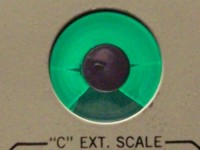
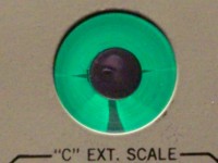
A magic eye tube is much less familiar although many readers may have seen one without realizing what they were looking at. Figure 4B.13 shows a magic eye tube. In A there is no power applied to the tube, in B it is fully open, and in C it is nearly closed. It can assume any state between open and closed depending on the applied voltage.
|
|
Figure 4B.13 The Magic Eye Tube in a Heathkit Capacitor Tester.
For a verbal description click here.
Here is the schematic diagram of a magic eye tube.
Figure 4B.14 Schematic of Magic Eye Tube Circuit.
For a verbal description click here.
The input goes to the grid of a triode amplifier which has a gain somewhere between 15 and 20 depending on tube type. When the voltage on the grid, pin 3, is zero the eye is fully open as shown in the left hand photograph above. Under these conditions the plate of the triode, pin 2 will be at about 25 or 30 volts.As the grid voltage is made negative, the plate voltage increases and the eye moves toward being closed as shown on the right above. The plate of the right hand triode is called the target and is the anode which is coated with the phosphor material as seen in the top picture above. The phosphor glows green when bombarded by electrons.
The grid of the right hand triode is called the "Shadow Control Grid" in Figure 4B.15 below. It is connected internally to the amplifier plate. The voltage on the "Shadow Grid" varies from a low of 25 volts to approximately 60 % of B+.
Figure 4B.15 Construction of Magic Eye Tube.
Not Exactly to Scale.
For a verbal description click here.
The target is not flat as it may appear in the drawing. It is shaped like a cup with a hole in the bottom. The angle of the sides coated with the phosphor is about 45 degrees. The "Shadow Rod" does exactly what its name implies, casts an electron shadow on the target. The "Shadow Rod" is connected to the cathode. When the "Shadow Control Grid" becomes more positive the "Shadow Rod" has less and less effect on the faster moving electrons and the shadow grows more narrow. The shadow rod and shadow control grid can be seen if you hold the tube at just the correct angle.These tubes were used frequently as tuning indicators in deluxe radios from about 1935 into the 1950s. Most people could tune a radio by ear so their functionality was questionable.
The writer has heard a story, maybe true, maybe not, that some unscrupulous salesmen were telling people that if you looked into the eye and tuned in the station absolutely perfectly you could see what was going on in the radio studio. Nobody could ever achieve the level of perfection necessary to see Jack Benny, Bob Hope, et al.
Fraudulent claims not withstanding, the magic eye was used as a record level indicator on real to real tape recorders, (there weren't any other kind back then). It also turned up on a 2 meter transceiver as a modulation and power output indicator, as well as on an SSB exciter. Magic eye tubes have been used by radio hams and audio hobbyist in many applications for years.
The cathode ray tube.
The cathode ray tube is the familiar, although now disappearing, picture tube in TV sets and computer monitors. It has also enjoyed wide application in radar, and even as the numeric readout in an early electronic calculator. But perhaps the place where the CRT has found its best usage is in the oscilloscope.If you told a service technician or maintenance engineer that he had to travel a great distance and work on an unknown piece of equipment, and he could only take one item of test gear, 999 out of 1,000 would take an oscilloscope. That 1,000th one would find himself up the proverbial creek without a paddle. An oscilloscope as it stands can measure voltage, time interval, and frequency. By the clever use of some resistors it can be used to measure current, resistance, capacitance and even transistor beta. Although there are digital multimeters that will measure all of these things the scope can still do something that no other test instrument can. That is show the shape of the wave. There are times when nothing will substitute for this.
The reader is referred to section 2.12 of this book for a detailed discussion of the cathode ray oscilloscope and its tube. There does not seem to be any point in repeating the information here.
Back to Fun with Transistors.
Back to Fun with Tubes."
Back to Table of Contents.
Back to top.
4B.5 Oscillators.
The very first vacuum tube oscillator was probably built by accident when someone was trying to get just a little more gain out of a radio frequency amplifier. If the plate circuit of a triode amplifier is tuned slightly higher than the grid circuit oscillation will most likely result. A parallel tuned circuit appears inductive when tuned high and one that is tuned low appears capacitive. The oscillation will take place between the resonant frequencies of the grid and plate circuits. The phase shifts that result will cause the feedback through the plate to grid capacitance to have a phase close enough to correct to sustain oscillation.TGTP (tuned plate tuned grid) oscillators are never used because changing the frequency requires turning the variable capacitors in two tuned circuits. If you want to play with one it usually helps to supplement the plate to grid capacitance with an external capacitor of 10 pf or so. If you use a pentode, the external capacitor is an absolute must.
Colpits and Hartley Oscillators.
The Colpits oscillator is distinguished by the fact that the capacitor is split in half and the junction of the two halves is often, although not always, connected to ground.In the Hartley oscillator the inductor is tapped and the tap may or may not be connected to AC ground. It also may or may not be connected to DC ground.
Figure 4B.16a shows a parallel fed Colpits oscillator. It is parallel fed because the DC plate current does not flow through the inductor. R3 may be replaced by an RF choke if desired. C3 keeps B+ from appearing across the variable capacitor which is generally a no no. If R1 were not present, C3 might not charge up and there would be B+ on the variable capacitor anyway. R1 makes sure that the inductor and the outer plates of the variable capacitor are held at DC ground potential. The tuning capacitor is sometimes known as a split stator but is actually the familiar dual ganged capacitor. The rotor and drive shaft are at both AC and DC ground potential.
The capacitor is, in effect, center tapped. This will place the center of the coil at AC ground potential. The effect of this is to cause the AC voltage at one end of the tuned circuit to be 180 degrees out of phase with the AC voltage at the other end. Since the plate voltage is 180 degrees out of phase with the grid voltage, the voltage fed back to the grid has the proper phase to reinforce and sustain oscillation.
The two halves of the variable capacitor need to be the same size or in a constant ratio to one another. If the oscillator is to be tuned over a narrow range, the capacitor on the plate side may be fixed and the variable capacitor on the grid side would have a fixed capacitor in parallel with it to limit its tuning range.
The AC voltage supplied to the grid is considerable. On the positive peak it drives the grid positive and C2 will be charged. When the grid is forced positive it begins to attract electrons to itself and current will flow. The grid acts like the anode of a diode. This current causes the capacitor to charge with the end of the capacitor which is toward the grid being negative. The grid never goes very far positive because the capacitor charges up and holds the charge. A small amount of charge leaks off through R2 but gets replenished on the next positive half cycle. A substantial average DC voltage, as much as -50 volts, is developed at the grid and this voltage makes the oscillator self adjusting. The negative bias lowers the gain of the tube and it will set itself to exactly what is needed to sustain oscillation. When the grid voltage goes negative, in most oscillators this will drive the tube into cutoff. This will cause the plate current to flow in short pulses but the tuned circuit rings like a bell and the waveform at the grid is a very good sine wave. The wave at the plate may not be as good.
Figure 4B.16 Parallel fed Colpits (a) and Hartley (b) oscillators.
For a verbal description click here.
Figure 4B.16b shows a series fed Hartley oscillator. Once again an RF choke could be used to replace R2. Capacitor C3 blocks the B+ voltage from the tuned circuit. Because the center tap of the coil is grounded there is no need for a resistor to ground. Neither side of the variable capacitor is at AC ground potential. An insulated coupling must be used between the capacitor shaft and tuning knob shaft to avoid the effect of hand capacitance. Hand capacitance would cause the frequency of the oscillator to shift when a person's hand came near the tuning knob.
Figure 4B.17 Two Series Fed Hartley Oscillators.
For a verbal description click here.
Series fed oscillators are more efficient and stable because there is no resistor in parallel with the tuned circuit to lower the Q. In figure A the B+ is tied to the center tap of the coil. This has the effect of placing both sides of the tuning capacitor at B+ potential. Even with insulated couplers from the capacitor shaft to the tuning shaft the "hot" capacitor is a hazard to someone servicing the equipment. That is why the tuned circuit has been moved to the cathode side of the tube as shown in B.This is still a series fed circuit because the cathode current flows through the coil. You will note that the tap has been moved from the center to near one end and that end of the coil has been grounded. This removes B+ from the capacitor and permits the drive shaft to be at ground potential.
The reason for moving the tap has to do with gain around the loop. A center tapped inductor gives phase inversion and unity gain. With the tuned circuit connected from plate to grid the tube provides gain enough to ensure the oscillator will start and keep going. In figure 4B.17b the tube is now a cathode follower which has a little less than unity gain. The coil acts as an auto transformer and steps up the voltage applied to the tap. The top to tap ratio is typically 10 to 1. The cathode follower does not invert the phase and neither does the coil since both connections are on the same side of the ground point.
The cathode coupled series fed Hartley oscillator has become the most popular oscillator circuit among receiver design engineers. In addition to the ubiquitous All American 5 it is found in short wave, and ham receivers from about 1940 on.
Figure 4B.18a shows a parallel tuned Colpits Oscillator. The inductor labeled RFC is an RF choke. It is used in place of a resistor to provide a high impedance to the oscillator and at the same time a low DC resistance. The tuned circuit requires a high parallel impedance. If a resistor were used it would have to be of such a high value as to reduce the plate current of the tube to a very low value. If it were lowered to get the plate current up it would adversely effect the Q of the tuned circuit.
Figure 4B.18 Two Colpits Oscillators.
For a verbal description click here.
Figure 4B.18b shows a series tuned Colpits circuit which is often referred to as a Clap oscillator. Wipe off that silly grin. Like the Hartley and Colpits circuits, the Clap circuit was named after the man who invented it. Capacitors C3 and C4 are comparatively quite large. I have seen circuits in which they were 0.005 microfarads. To resonate with these capacitors at 4 MHz the inductor would have to be quite small, 0.633 microhenrys to be exact. Such a small inductor would be about one turn and would have a low Q at 4 MHz. In actuality the series tuned circuit has a normal inductor of many turns and a capacitor of 100 or 200 pf.Remember that a series tuned circuit has minimum impedance at resonance. Just a little off resonance, on the high side, it is still a low impedance but appears inductive. A low inductive reactance means a small apparent inductance. It may seem as if the Q is low but the basic LC circuit has a high Q which will make the oscillator very stable.
Oscillator Stability.
There is nothing in the diagram of an oscillator that would indicate it would be anything but perfectly stable. That is, you could set it to a given frequency and it would stay there forever. The reality of oscillators is not even close to that. An LC oscillator will drift in frequency and unless steps are taken to minimize the drift it may be unusable for the desired function.As the last sentence of the previous paragraph indicates, the drift of an oscillator can't be eliminated, just minimized. Let's first examine the causes of drift and then see how they can be minimized.
The main cause of frequency drift is a change in temperature. In vacuum tube equipment the heat generated by the tubes is unavoidably transferred to the elements of the tuned circuit.
As the inductor warms up the wire making up the coil gets longer. The form on which the coil is wound gets larger in diameter, and all that translates into a larger inductance.
In an air capacitor such as a variable, The plates get bigger and farther apart. Those two effects may seem to cancel each other and they do to some extent. In ceramic and mica capacitors the dielectric, (insulator), usually has a temperature coefficient all its own. This can be adjusted by the manufacturer to give a capacitor a positive, zero, or negative temperature coefficient.
The coil is sitting there with its big positive temperature coefficient so if we can incorporate a negative coefficient into the resonating capacitor this will go a long way toward making the oscillator stable.
Another source of instability is the change in tube capacitance. This change occurs much faster than those caused by warming up of the coil and capacitor. An attempt to compensate for changes in tube capacitance could result in an oscillator that would drift down in frequency until the tube reaches its operating temperature and then up as the coil and capacitor start to feel the heat from the tubes.
The trick here is to make the fixed capacitors in the circuit so large that the tube capacitances will be a small part of the total. In any of the circuits the capacitor can be made larger and the inductor smaller. This can only be carried so far. This will result in a lower Q because a coil which is too small for the frequency will have more resistance in relation to its inductance.
The parallel tuned Colpits goes somewhat in this direction. The ARRL Radio Amateurs Handbook recommends for an oscillator to tune from 3.5 to 4 MHz, that C3 be 680 pf and C4 be 0.0022 uf. For the Clap oscillator they recommend that C3 and C4 both be 0.001 uf. Although the writer once owned a VFO, (Variable Frequency Oscillator), made by E. F. Johnson that used 0.005 uf capacitors for C3 and C4.
Electron Coupled Oscillator, (ECO).
You may be wondering how to get the signal out of these oscillators. In all cases the best waveform is found at the grid although this is a very high impedance point and a lot of isolation would have to be included to keep changes in load from effecting the frequency. For the cathode coupled circuits the output signal could be taken from the cathode which is a low impedance point. Even so changes in load can cause the frequency to change quite a lot. The solution is to use a pentode and take the signal off the plate, as shown in Figure 4B.19.

Figure 4B.19 Electron Coupled Clap Oscillator.
For a verbal description click here.
This is called an Electron Coupled Oscillator because the screen grid takes the place of the plate in the triode circuit and the signal is coupled to the plate by the electrons that pass through the screen.Notice that the screen voltage needs to be regulated and it doesn't hurt to regulate the plate voltage as well. The tuned circuit in the plate serves to clean up the waveform which is not a good sine wave if a resistor is used. R2 lowers the Q of L2 and C6 so it does not have to be tuned along with C1 and L1.
This oscillator can be plugged into the crystal socket on a 50 or 75 watt transmitter. If used as part of a transmitter it should be followed by a class A pentode stage before going into the class C stages. If used in a receiver or transceiver the output could probably be fed straight to the mixer.
Crystal Oscillators.
One solution to oscillator drift is to use a quarts crystal. If quarts crystals are cut in a certain way they are piezoelectric. Which means that if an electric field is placed across them, one or more of its mechanical dimensions will be altered. Conversely, if mechanical force is applied an electric potential will be developed. The process is known as bilateral which means it works both ways.The crystal is cut into thin rectangular plates along a particular axis of the crystal. The subject of quarts crystals can fill a book all its own. No attempt will be made here to delve into the various orientations in which a crystal can be cut.
Every physical object has a mechanical resonant frequency. Some are low enough to hear such as a common drinking glass filled, or partly filled, with water. Early TV remote controls used aluminum rods about 3/8 inch in diameter and about 2 inches long. When one of these rods was struck on the end it would ring at a frequency above the range of human hearing. A specially designed microphone in the TV set would pick up the ultrasonic frequencies and after amplification a set of tuned circuits allowed the particular rod being struck to initiate the corresponding function. The tiny plates of quarts have mechanical resonant frequencies that are in the radio frequency range. When this mechanical resonance is translated into electrical resonance by the piezoelectric effect, the crystal exhibits the resonance of the circuit of Figure 4B.20a.
Figure 4B.20 (a) Equivalent Circuit of a Quartz Crystal,
and (b) Colpits Crystal Oscillator.
For a verbal description click here.
Because the series resonant circuit has a capacitor in parallel with it the overall effect is for the crystal to have a very low impedance at its series resonant frequency, and just a few hertz higher, a high impedance at its parallel resonant frequency. When ordering crystals you must specify which of the resonant modes you plan to use and if parallel, how much capacitance will be across the crystal.Figure 4B.20b is the circuit of a Colpits oscillator. It operates the crystal in its parallel resonant mode. There are many crystal oscillator circuits but this is by far the best one for almost all crystals. Typical values for the capacitors are 33 pf for grid to cathode and 100 to 220 pf for cathode to ground.
The output may be taken off the cathode or if a cleaner waveform is desired a pentode may be used with a tuned circuit in its plate circuit as shown in figure 4B.19 above.
There is only one way to change the frequency of a crystal oscillator. Order a new crystal and when it comes in the mail, plug it into the socket. That's the price to be paid for a high degree of stability. In Chapter 9 of this book we will study the frequency synthesizer which gives both the agility of a tunable oscillator and the stability of a crystal oscillator. It would not be practical to construct one of these devices with vacuum tubes.
Back to Fun with Transistors.
Back to Fun with Tubes."
Back to Table of Contents.
Back to top.
4B.6 Problems.
- The plate resistance of the pentode section of a 6U8 is 0.4 Meg ohms. The RC amplifier data for it is as follows.
Ebb = 250 volts.
Rb = 270 k ohms.
Rcf = 1.0 Meg ohms.
Rc2 = 820 k ohms.
Rk = 1200 ohms.
Vin = 0.1 v.
Vout = 22.0 v.
Gain = 220.
% Dist = 0.82 %.
Calculate (a) the transconductance of the pentode under the above conditions, and (b) the gain of the amplifier if the cathode bypass capacitor is removed and the screen is bypassed to the cathode.
- A ham band receiver has a first IF of 2250 kHz, and the local oscillator operates above the incoming frequency. If the receiver is tuning the 3.5 to 4.0 MHz band what is the frequency range of the image?
- A doubly balanced mixer has the following input frequencies, 3.5 MHz, and 60 kHz. What frequencies will be present in its output?
- A singly balanced mixer has the following input frequencies, 1.5 MHz to the balanced input, and 2.5 MHz to the unbalanced input. What frequencies will be present in its output?
- The AGC voltage of a radio receiver is about -1 volt between stations and changes to -10 volts when a particular station is tuned in. A tuning eye (magic eye tube) in this radio will be,
(a) closed when between stations and open when a station is tuned in.
(b) open when between stations and closed when a station is tuned in.
- A wave on an oscilloscope is 3.4 cm from the lowest to the highest point and 2 complete cycles cover 8.7 cm. The controls on the scope are set as follows. Vertical to 50 milli volts/cm and time-base to 20 nsec/cm. A times 10 probe is in use. What is the RMS voltage of this wave?
- A wave on an oscilloscope is 3.4 cm from the lowest to the highest point and 2 complete cycles cover 8.7 cm. The controls on the scope are set as follows. Vertical to 50 milli volts/cm and time-base to 20 nsec/cm. A times 10 probe is in use. What is the frequency of this wave?
- An oscillator with a tapped coil is a;
(a) Hartley.
(b) Colpits.
(c)Clap.
- An oscillator with the inductor and variable capacitor in series is a;
(a) Hartley.
(b) Colpits.
(c)Clap.
- In an oscillator employing a tapped coil, When the coil is connected to the plate and grid the tap is;
(a) at the center of the coil.
(b) near one end.
- In an oscillator employing a tapped coil, When the coil is connected to the cathode and grid the tap is;
(a) at the center of the coil.
(b) near one end.
- In any of the oscillator circuits employing a triode tube the best waveform is found at;
(a) the cathode.
(b) the grid.
(c) the plate.
- In an ECO the signal is coupled from the oscillator to the output by;
(a) capacitive coupling.
(b) magnetic inductive coupling.
(c) the electrons inside the tube.
Back to Fun with Transistors.
Back to Fun with Tubes."
Back to Table of Contents.
Back to top.
4B.7 Answers to Problems.
- (a) 1,585 micro mhos, (b) 98.0.
- 8.0 MHz to 8.5 MHz.
- 3440 kHz and 3560 kHz.
- 1.0 MHz, 2.5 MHz, and 4.0 MHz.
- (b)
- 1.7 volts.
- 11.5 MHz.
- (a)
- (c)
- (a)
- (b)
- (b)
- (c)
Back to Fun with Transistors.
Back to Fun with Tubes."
Back to Table of Contents.
Back to top.