
A number of people have inquired as to how we went about determining how we were going to modify the front brakes. Therefore, we've created this technical section to cover such subjects.
We originally purchased some naturally aspirated 300ZX rotors and calipers off a friend, intending to use both items in the conversion. However, having machined out the hole in the centre of the 300ZX rotor to allow it to side over the hub (200B) it soon became apparent that these rotors were not going to work. The height of the mounting bell (or "hat" of the rotor) was too tall, pushing the rotor towards the strut. This resulted in the rotor fouling on the lower control arm. We evaluated a number of different options including cutting the mounting bell off and replacing it with an alloy item, but decided the best solution was to simply find a better fitting rotor.
In order to determine what rotor we to use, we first needed to take some measurements. The primary factor governing the fitment of the whole assembly was the height of the mounting bell; too tall and the rotor would foul on the suspension (as with the 300ZX rotors), too short and the rotor would bring the brake caliper too close to the wheel. The first thing we tried was getting a standard 200B assembly (hub and disc rotor bolted together) and sitting this inside an upturned wheel with the 300ZX caliper sitting over the 200B rotor. The reasoning behind this was that a 200B rotor obviously had decent clearance between itself and the suspension. If we could use the overall height of the 200B rotor (i.e. the height from the top of the hat to the back of the rotor) as a guide, we would have a starting point. As it turned out, the caliper did not foul on the wheel - although it was close. We then took bolted a strut to the hub/rotor assembly and sat it back in the wheel. There was amble clearance between the caliper and strut (as you'd expect), hence we decided to use the overall height of the 200B rotor as our baseline for the new rotor.
The next job was to measure the other critical dimensions of the 300ZX rotor. These were rotor thickness (25mm) and rotor diameter (280mm). This information is crucial as brake calipers are manufactured with a specific rotor diameter and thickness in mind. They are machined to fit that particular size rotor and to use anything else is risky and can throw up problems.
Now we had the critical dimensions, we took some other measurements, such as the size of the hole in the centre of the rotor (to fit the hub) and the number of wheel studs the rotor was designed for. This last factor isn't critical, but a 5-stud wheel will always have one of the holes become a slot when the rotor is redrilled. We would try and avoid this if possible.
Having obtained the critical dimensions (280mm diameter, 25mm thick and 28mm overall height), we then went to the Disc Brakes Australia (DBA) book and started looking for rotors with these matching dimensions. After an hour or so of research we had come down to a shortlist of about 8 rotors which were all close enough to do the job. We then culled this shortlist further by arranging the rotors in order of purchase price. At this stage we checked the rotors for best match with regards to the number of studs and centre hole diameter. Having considered all these factors, we selected the rotor with the best fit and lowest price. It turned out that 2 rotors looked to be ideal - both SAAB rotors. We eventually decided on the DBA431 as it had the taller hat, meaning less likelihood of the caliper being forced into the wheel, while still being shorter than the 200B rotor. The caliper hitting the wheel could always be fixed with wheel spacers, but a straight fit would be preferred.
We purchased the rotors and then considered what was needed to fit them. Being we'd done our research it turned out that there wasn't a great deal of work to do. The first thing we did was go to see a friend, who kindly machined the centre hole out on his lathe (many thanks again Jason). From here we took the rotors home and made up a template of the 200B hub-mounting pattern. We then overlaid this pattern over the rotors and drilled the holes to allow the hub mounting bolts to pass through the rotors. The rotors were now mounted.
The next item on the agenda was mounting the calipers. We had heard many rumors that R31 struts allowed these sorts of calipers to bolt straight on. Being the struts had already been significantly modified for other reasons, changing struts was simply not an option. Therefore we had to fit the calipers to the 200B struts we had.
In order to determine how to mount the calipers, we bolted the rotors to the hubs, the hubs to the struts and then slid the calipers onto the assembly. It wasn't pretty. No matter where you sat the caliper, there was absolutely NO way we could use the original mounting brackets. A number of people have suggested that we didn't try hard enough to find a way - sorry but 2 hours of measuring, contemplating and dummy fitments were enough! :) The problem lies in the fact that the rotor is only 280mm in diameter - trying to use the original bracket ends in having the caliper sitting half off the rotor - an unacceptable situation. So at this point, we concluded we would need new caliper brackets. We spoke to a number of people about this and it appeared to be quite a tricky job. The trick to doing this job is to understand that the new bracket has to be welded to both the strut tube (extruded mild steel) and the stub axle forging (forged MS). To weld to the forging it is necessary to first preheat the metal, complete the welding and finally cool everything in a lime bath. Whilst not rocket science it's certainly something which require consideration - this is brake components we're talking about here!
After discussing the situation with a number of friends, one person suggested giving one of the local fabricators a call. Another friend had recently had this person (Rod) make up some brackets and he'd done a great job for a very reasonable price. So we got on the phone to Rod and asked him how much it would cost to have the brackets made and welded on. His quote was $120 for both. Rather than go through the hassle of doing it ourselves, we gave Rod the money and 2 days later had the struts back ready to go. The final phase of the project was simply to assemble it. This was obviously a simple case of bolting the rotor/hub assembly onto the strut and bolting the caliper over the top of it. From there we simply bolted it into the car and hooked up the brake hose. Now is probably a relevant time to mention that we run braided hose with banjo fittings, not the standard rubber hose. This meant that the fitment of the hose was simply a case of rotating the fitting.
It is here that I will again remind the reader that this isn't a "How To" section. This setup will likely not work unless ALL of the components are EXACTLY the same as we used, down to the offset of the wheels on the car.
Making of the Quad Throttle Body Manifold
Most of this information has been moved from the Car Details section. I have tried to up date and expand on it as much as possible.
As a bit of short background, the reason for deciding to make this manifold as opposed to having it done professionally is that we couldn't find anyone who could make if for a reasonable price. It also had to be made to some fairly out of the ordinary specifications and understanding the bigger picture helped a great deal in the design of it. There had been 2 ways to approach the construction of the manifold. The first was to make 2 flanges (one to bolt to the head, the other to bolt to the throttle bodies) with connecting runners, the second was to do it with the plates of alloy. The latter method was chosen for the following reasons:
Having decided on a method of construction, it was then necessary to determine how to approach the job. When trying to scratch build something, it's not a good idea to just get the material and hacking away - something inevitably gets missed (from experience). So we went through the process from start to finish on paper. It was determined that the first job was to mark out the plates with the information which would be needed to make the finished product.
The first step was to choose a "head" plate and a "throttle body" plate. We then chose an outer surface and an inner surface on each. The inner surfaces would mate together, while the outer surfaces would mate with the head and throttle bodies respectively. For the inner surfaces we chose the faces with the least amount of damage (scratches, dings and the like) as these would need to seal air tight without gaskets.
With the faces chosen we then symmetrically broke up the outer faces - this consisted of a line half way through both the vertical and horizontal axis of the plates (i.e. a cross). We then got the old inlet manifold gasket and marked it similarly. Given that we didn't have an old throttle body gasket, we made up a template from cardboard. This simply involved dummy assembling the carbies together, taping the cardboard to the manifold face (of the carbies) and using a hammer to tap out all the relevant holes. This template was then also broken up symmetrically.
At this point the manifold gasket and the throttle body template were taped to their respective alloy plates and the information transferred across - i.e. we traced all the holes onto the alloy plates. Having marked out our plates, the next step was to bolt them together.
It has probably now become obvious as to why we needed to mark the plates first - to avoid our mounting bolts falling somewhere inconvenient. We now had to figure out the best way to fasten the plates together. We decided to use cap screws (alan head bolts) which we would countersink into the top (throttle body) plate. In order to ensure there was an even distribution of clamping force, we decided to use 3 across the plate. It is at this point that I should say that we're still unsure as to why we didn't use button head cap screws (countersunk cap screws)....a slight brain fade I'd suggest. Anyhow, we decided to use full-headed screws. At this stage, the top (throttle body) plate was evenly divided into 4 and 3 holes marked for the fastening bolts. We then overlaid the throttle bodies on the top plate and noticed that the throttle linkage could be a problem if the middle bolt was mounted in the centre of the plate. For this reason it was decided to move it slightly towards to top of the plate for clearance. We then clamped the 2 plates together using G-clamps and put the assembly in the bench drill. Using a drill bit small enough to still be able to use a tap for the mounting bolts, we drilled through the top plate and 1/2 way into the bottom plate. This was done for each of the 3 bolts. At this stage we disassembled the 2 plates.
The next job was to tap the bottom plate to accept that mounting bolts. This is a fairly self-explanatory step, hence I won't expand further. The next thing was to tackle the top plate. First we selected a drill bit big enough to allow the mounting bolts to slide easily through the top plate. Each of the 3 holes was then redrilled. The next step comes back to using those full-headed cap screws. It was obviously necessary to countersink the heads of these so as they didn't foul on the throttle bodies. In order to do this we purchased a drill bit with a slightly larger outside diameter than the head of the cap screw. We then drilled each of the holes with this to around 1mm shallower than the height of the cap screw head. At this point, we ground the head of the drill bit flat - turning into something akin to a milling bit. We then milled/drilled the last 2mm of each of the holes. At this point the plates were assembled.
The next step in the process was to enable a method of mounting the throttle bodies to the manifold. Having already marked the top plate, we knew where the mounting bolts would have to go. It was therefore a simple process centre punching each of these markings, selecting the correct drill bit (one which would be the correct size to allow tapping of the hole) and drilling through the top plate and 1/2 way into the bottom plate. The next step was to then over drill the holes in the top plate to allow the studs to slide through easily. We then tapped the bottom plate to accept these studs.
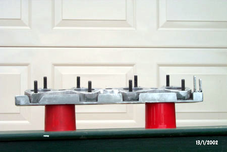
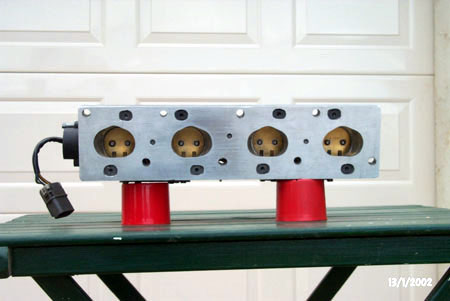
Having ported the manifold we were most of the way there. We decided to reshape the top plate to mirror the throttle bodies, to save a bit of weight. Having done this, we did an assembly on the head with the throttle bodies. It was at this stage, while investigating the positioning of the fuel injectors, that we discovered that there wasn't going to be enough room to fit the airbox under the bonnet. After much tooing and froing, we took the throttle body assembly out to Brian (Neal Bates Automotive) and asked for his input. Brian suggested the bottom plate be machined at an angle to lower the ends of the throttle bodies. Being this was the best option, we ran with it and Brian machined the bottom plate. these views give a good indication of what was done:
Vollah.....one manifold.

Once we got the assembly back from Brian we needed to tidy up the ports in the manifold a little, as they now no longer matched exactly. This only took an hour or so and didn't require much of a change in the shape of the ports. It was at this stage we decided to do away with the studs as the method of mounting the throttle bodies. 3 of the holes had stripped threads and 2 others were loose. This could possibly be put down to poor quality alloy, but whatever the reason, it was unacceptable. Instead we decided to drill though both plates and mount bolts in from the bottom plate.

The process was started by using the top plate as a template and drilling the holes all the way through the bottom plate. We then purchased appropriately sized bolts and ground the ends of them into something akin to an ellipse with flat edges. We then used to die grinder to form a matching hole in the bottom plate. This way they wouldn't rotate when mounting the throttle bodies. The next step was to fasten them in place. This was done using the large drill/mill bit again, countersinking holes in the top plate for some nuts. This done the plates were totally disassembled, the inner surfaces cleaned and a large bead of Permatex Ultra Grey added. The plates were then bolted back together.
If there is a specific area of modification you would like to be included in this section, please email us and we'll endeavor to include it as soon as we can. The only area of modification I am not willing to go into at this point is exactly what has been done to the cylinder head. This is because my friend who chose the path of modification has a business doing this sort of work. Feel free to contact me for his details if you would like to talk to him.
Main Page ::
What's Group 3J? ::
What's Happening? ::
Dyno Results ::
Car Details ::
Car Specs ::
Suppliers ::
War Stories ::
Links
