
For a verbal description click here.
===About this page.===
As I composed this page I seem to have lost sight of my original goal. This series of articles is meant to be a tutorial on the audio amplifier explaining how each part of the circuit works. Although I have already revised this page once, it still goes too deeply into design criteria such as distortion, gain, and output level. I have now performed another revision in hopes that I can keep my eyes on the prize and leave the design information to the article titled "Phase Inverter/Driver, the Heart of an Amplifier" in the section titled "Designing and Building Audio Amplifiers". At the same time I have added more information to the page which is linked above as well as eliminating redundant text and figures.Now to the article.
In order to properly drive a push-pull output stage of an amplifier we need two signals of equal voltage and opposite phase or sign. Getting these signals is easy in theory but can get complicated in practice. Let's begin at the beginning.Open Loop Phase Inverter.
So how do you get two signals of equal voltage and opposite phase? The engineer who designed the first push-pull output had to answer that question and there was no one he could ask who had done it before. Well, an ordinary common cathode resistance coupled amplifier inverts the phase of the signal so all we need to do is to run the signal for the second tube through one more stage than the first. But hang on just a minute, the signals have to be equal in voltage and a resistance coupled amplifier amplifies the signal. OK; so let's put in a resistive attenuator to decrease the signal by the same amount that the amplifier amplifies it. You mean like this?
For a verbal description click here.
Yeh, that's it. You don't want to use a tube that gives a whole bunch of gain like a 12AX7 so a 12AU7 is better. The first stage is just to get up some gain to be later traded off for other improvements by applying feedback. The output of the second stage drives the grid of one of the outputs. Notice how the grid resistor of that output tube is tapped for a small amount of the voltage to be taken off to the grid of the third stage. This inverts the signal for the other output tube.A little while ago I picked up an old Philco radio at an antique mall. When I started examining it I found to my surprise it had a push-pull output. It was made in 1937. I don't know when negative feedback found its way into consumer products but it was after that. The Philco used exactly this same circuit (with different tubes of course, and no feedback). The drive balance of the Philco circuit was within 5%.
The circuit shown above produced amazingly good balance after I got the resistor values right. I swapped out several tubes and the worst imbalance I could get was about 5 percent. Its chief problem is asymmetrical distortion. When operated at a level sufficient to drive a pair of 6V6s the distortion was 1.9 % from the top output and .25 % from the bottom. At a 6L6 level the distortion was 2.1 % and .3 %. I'll bet some of you are scratching your heads and saying "hmmm, he must have reversed those readings, after all the bottom output passes through one more stage than the top so it should have more distortion." No, I double checked it and then checked it again. What is going on is? The two amplifier stages are operating at the same level and so are acting like a push-pull amplifier and canceling even harmonics. Since most of the distortion is second harmonic most of it gets canceled out. You can also think of it as the third stage is correcting the errors of the second. This asymmetrical distortion seems to be an incurable plague of phase inverters.
I tried many variations on this circuit in an attempt to clean it up. When I did find something that equalized the distortion it was at the higher level not the lower. Let's look at a circuit with some correcting feedback.
Closed Loop Phase Inverter.
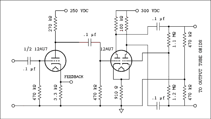
With a few modifications the simple open loop phase inverter can be turned into a closed loop inverter that will self correct any imbalance between outputs.First of all you will note that instead of two separate cathode resistors each with its own bypass capacitor, there is one cathode resistor in common and no capacitor. If there is an imbalance in audio current between the two cathodes a voltage will be developed that has the proper phase to partially cancel the imbalance.
Also the grid of the right hand triode is fed from a voltage divider but with a difference. Instead of connecting from the plate of the first triode it is connected between the two plates, (with DC blocking capacitors). The resistors have to be unequal, 1.1 megohm and 1.2 megohm, or there would be no signal to the grid if perfect balance had been achieved. When the balance is just right the signal to the grid of the right hand triode is also just right.
These measures combine to keep the outputs balanced as resistors and tubes change due to ageing.
Long Tail Pair.
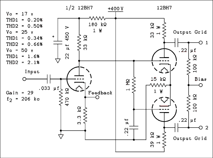
A phase inverter circuit often used in high fi and guitar amplifiers is the long tail pair. This is in current terminology a differential amplifier. The one shown below is a direct coupled version and is a variation of one used in a commercial amplifier that had cathode loaded output stages. It had to be capable of delivering 50 volts RMS per grid.
For a verbal description click here.
Circuits similar to this were used in amplifiers made by Eico and many others. Note that the asymmetry of distortion has diminished from about 7 to 1 to about 2 to 1.The DC plate voltage on the first 12BH7 is applied directly to the grid of the upper triode in the LTP (long tail pair) and to the grid of the lower triode through a low pass filter consisting of the 1 Megohm resistor and 0.22 uf capacitor. This places both grids at the same DC potential while applying signal only to the grid of the upper triode. The 15 k ohm resistor in the cathodes sets the plate current to the correct value for proper operation.
The AC signal which is applied to the grid of the upper triode causes a variation of plate current as in a normal amplifier. This varying current, which is in phase with the grid voltage, flows through the cathode resistor as well as the plate resistor. The varying current in the cathode resistor causes a voltage variation which is in phase with the grid signal. This voltage is directly coupled to the cathode of the lower triode in the LTP. The grid of the lower LTP triode is grounded for AC through the 0.22 uf capacitor. This makes it a grounded grid amplifier.
In normal Class A operation the grid has a negative DC bias on it. In this case the grids are at about 90 volts while the cathodes are at about 100 volts. When the AC signal drives the cathode of the lower triode more positive the grid and cathode are becoming farther apart. This is an increase of the bias which results in a decrease of plate current. We see that the plate current in the lower triode is out of phase with the plate current of the upper triode. If they were exactly equal they would completely cancel and there would be no voltage variation at the cathode to change the bias on the lower triode and there would be no plate current variations. Oops? This contradiction means that the plate current variations in the lower triode are not as large as those in the upper triode. To have the same output voltage from both triodes in the LTP the load resistor of the lower triode must be slightly larger than the load resistor for the upper one.
Lets look at it from the standpoint of current. The upper tube is producing cathode current. Some of this alternating current flows to ground through the 15 k ohm resistor and the rest enters the cathode of the lower tube. If you write the equation IR + IV2 = IV1 you see that the currents in the two tubes are 180 degrees out of phase. If the resistor could be made infinite for AC while still passing DC the alternating currents in the two tubes would be equal and the load resistors could be made equal. The larger the common cathode resistor, the better the balance.
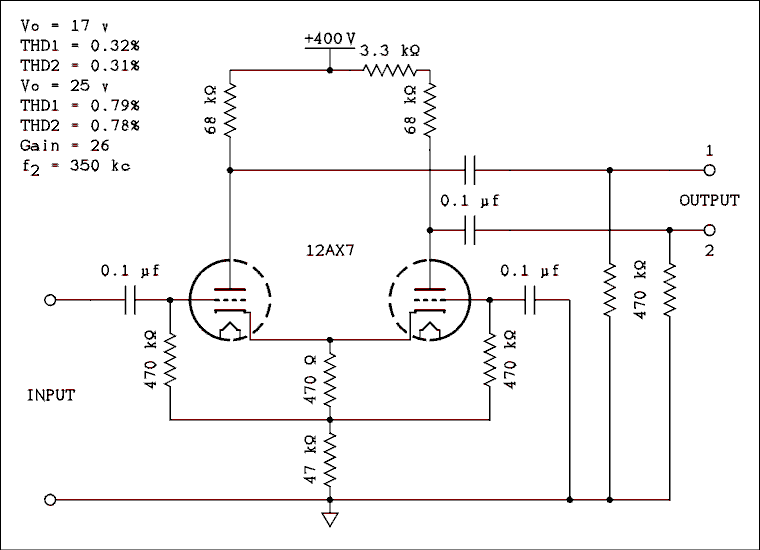
Another variation you are likely to see in commercial amplifiers is the simple long tail pair shown below.
For a verbal description click here.
As you can see from the legend, the asymmetry of distortion has all but disappeared. The inequality of plate load resistors is also much smaller.Because the 12AX7 is a low power tube this circuit can't drive a pair of tubes having 100 k ohm resistors in their grids. This inverter would be found in a cathode biased amplifier or there would be another pair of amplifier tubes between the inverter and the power tubes.
If a constant current sink is used instead of the resistor in the cathode circuit the circuit will come into perfect balance with equal plate resistors and the distortion will be very low and equal. A constant current sink has an extremely high impedance for AC, nearly infinite, while passing the DC to set the operating point of the tubes. But I have never seen this circuit arrangement in any commercial amplifiers.
Phase Splitters.
The formal name of this circuit is the "split load phase inverter". That's because the load resistor has been split in half and one half has been moved around the circuit to be in the cathode. This gives two voltage outputs of equal amplitude and opposite phase.Here is the circuit used in that little Newcom amplifier which was part of my first high fi system.

For a verbal description click here.
The first section of the 12AX7 is operated in a mode called, not quite correctly, zero bias. The ten megohm resistor allows the grid to develop about -0.7 volts of bias. This is because electrons randomly run into the grid wires on their way to the plate. The 100 ohm resistor in the cathode does not contribute any significant amount of bias voltage, it is there so negative feedback can be applied from the output transformer secondary. This stage has a gain of approximately 73. Signal is coupled from the plate of this amplifier by the .01 microfarad capacitor to the grid of the second half of the duo triode. This is a cross between a cathode follower and a common cathode stage. Because the tube is a triode the cathode current is identical to the plate current (not so for a pentode). with identical currents flowing through the two 100 k ohm resistors the voltages across them are identical, if the resistances are identical. Obviously the current flows in the same direction, up or down, in each resistor at any instant of time. Because the signals are taken one off the top end of a 100 k ohm resistor and the other off the bottom of the other 100 k ohm resistor the two signals are opposite in sign or phase. The gain of this circuit from input to either output is approximately 0.9.If the grid were placed at DC ground by connecting the 470 k ohm resistor to ground the voltage drop across the 100 k ohm resistors would not be enough to produce the necessary 40 volts peak to peak which is required to drive a pair of 6V6s. By connecting the grid return resistor to the top of the 100 k ohm resistor and then using a 10 k ohm to bias the tube the plate current is large enough to produce the necessary drop, about 25 volts, across each 100 k ohm resistor. Connecting the grid resistor where it is tricks the tube into "believing" that it has 10 k ohms in its cathode instead of the 110 k ohms which is really there. (That's called anthropomorphizing). The grid bias is the DIFFERENCE in voltage between the cathode and the grid not the voltage between the grid and ground.
Because the lower end is connected to a point which receives signal, the effective resistance of the grid resistor is different from 470 k ohms. Let's say that the voltage at the grid rises by 1 volt. The lower end of the grid resistor will then rise by approximately 0.9 volts. The change in voltage across the resistor is only 0.1 volts. The current through the resistor will change by 0.1 volts / 470 k ohms = 0.213 microamps. The effective resistance of the resistor is change in applied voltage divided by change in current = 1 volt / 0.213 microamps = 4.69 megohms. This allows the use of a smaller coupling capacitor than would otherwise be required.
The circuit performs better than I had expected. I had never tested it before because back when I was building my tube circuits I didn't have much in the way of test equipment. The over all gain is 66 based on just one of the outputs, either one. The distortion is 0.3 % at the level required to drive 6V6s to full power and 0.9 % for 6L6s. Not bad when you look at the distortion figures given in a tube manual for these tubes, 6V6 3.5 % distortion at 14 watts and 6L6 2 % distortion at 26.5 watts. In the final installment of this series we will discuss the benefits of negative feedback and the drawbacks of using too much of a good thing.
Direct Coupled Phase Splitter with Drivers.
The Williamson amplifier circuit was very popular through the 50s and 60s. It was developed in England and quickly adopted and adapted to American valves, er, tubes. The British version of the 6SN7 valve had slightly different characteristics than the American 6SN7 tube. A few value changes made it work as well as it had in England and the circuit was used in many commercially made amplifiers as well as home brewed projects.
The Williamson Circuit.The output stage usually employed tubes that were somewhat higher power than the operating point would require, such as 807s in a 25 watt amplifier. It was felt that this gave lower distortion than for a pair of tubes pushed to their limit. It certainly gave longer tube life.
The sections that made a Williamson amplifier, a Williamson amplifier, were the split load phase inverter and driver. The circuit is given below.

For a verbal description click here.
The circuit will look familiar but different. The plate of the first amplifier is directly coupled to the grid of the split load phase inverter rather than through a capacitor. Although this saves one capacitor and two resistors, reducing component count is not the purpose of this modification. It is to eliminate one RC time constant from the signal path. The fewer there are the better global feedback will behave. In the circuit above the grid is already at a positive potential and of course so is the plate. Why not make them the same and eliminate the capacitor.The performance is as follows. At an output level of 17 volts per grid the distortion produced by the driver is 1.3% at the upper plate and 1.35% at the lower plate. At 25 volts output the driver produces 1.85% from the upper plate and 1.92 from the lower.
The voltage gain from input to one of the outputs is approximately 140.
Next; Push Pull Outputs.Or use your "Back" button to return to where you were.
Thank you for visiting my page at Angelfire.
Please come back and visit again!This site begun March 14, 2001
This page last updated October 3, 2014.