For a verbal description click here.
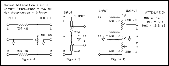
In a perfect world we wouldn't need balance controls. Do I even need to say it? The gains of both channels of a stereo amplifier are so close to being identical that no human ear can tell the difference. After 40 years, control manufacturers have learned how to make two ganged audio taper pots that are just as good, but that is about as far as perfection goes. The weakest link in the chain is the listening room. Few of us are rich enough to have our houses especially designed and built including a listening room which has perfect symmetry. With one speaker in a corner and the other next to a hallway and an open doorway to another room the sound is far from perfect. And just for good measure the speakers themselves can be quite different even though they are from the same manufacturer, same model and bought at the same time from the same store. The other large variable is the source of program material. New recordings are much better, but some of those early stereo recordings are pretty bad. In those days the engineers had been raised on monophonic and didn't quite know how to deal with "this new thing called stereo". With all that going against us we find ourselves needing balance controls.The earliest stereo phonographs solved the problem by having two volume controls. That saved them the additional expense of two dual ganged pots (one for volume and one for balance), but it wasn't very easy to adjust especially if you had to get up to make an adjustment and then sit back down to hear how it sounded. Consumers soon demanded ganged volume controls and a balance control. The simplest kind of balance control is shown in figure A.

For a verbal description click here.
In most implementations of this circuit the 510 k ohm resistors were the output resistances of the amplifier stages just before the balance control. I own a piece of commercial equipment which uses this type of control and I used one with this type of control that belonged to the university where I taught for many years. I never cared for its operation. All that can be said in favor of this control circuit is; it is simple and inexpensive. Against it are its relatively high insertion loss and that most of the effect is near each end of the control's rotation.When the control is set to its center position each channel is fed from a voltage divider consisting of the 510 k ohm resistor and half of the pot, 250 k ohms. That gives 9.6 dB of attenuation. When the control is set to the full right position (wiper at the top) the left channel is shorted out to ground so there is no output. The right channel is connected to a voltage divider consisting of the 510 k ohm resistor and all of the 500 k ohm pot. This gives an attenuation of 6.1 dB.
The circuit of Figure B is the one used in most commercial integrated amplifiers and preamplifiers. It uses a very special control. For half of the control there is no resistance and all of the resistance is in the other half. It is a dual control and one part is the reverse of the other. The schematic symbol shows a rectangle indicating no resistance for half of each part and resistance for the other half. When the control is set to the center of rotation the output for each channel is the same as the input. That means zero dB insertion loss. As the control is moved off center, say to the left, the right hand channel experiences attenuation while there is no change in the volume of the left channel. I'm not particularly fond of this system either because it's not a constant volume pan (moving the sound from one side to the other). If you have a program with a serious imbalance you have to turn the balance control to one side and then crank up the volume to compensate. I have never seen these special pots on the hobbyist market. Can you think of a better reason not to use this circuit?
Now to Figure C. It is what I used in my tube preamp years ago. It uses a dual ganged linear pot. These are not hard to find on the surplus market. You could leave out the resistors above and below each pot but the control would exhibit the problems associated with using a linear pot as a volume control. It has enough range to compensate for a 9.8 dB imbalance. Although it's not exactly a constant volume pan it comes pretty close. All in all it's about the best balance control a hobbyist can use. It can be implemented with any dual linear control, the fixed resistors should be as close to 1/2 of the pot's resistance as you can come with standard values.
Electronic Remote Controls.
My transistor and IC preamp uses doubly balanced mixers as electronic attenuators and the functions of volume and balance control work through those circuits. This means single controls with nothing but DC control voltage on them making long wires and a chair side control panel possible. I chose DBMs because of their low distortion and noise. Implementing such circuits with tubes seems much too daunting a task and besides I don't think the distortion could be kept very low. I don't know if remote cutoff pentodes would be any better and likely worse. That's something for future experimenting. Meantime remember the KISS rule (keep it simple stupid).