
|
|
||
|
3. Points and Polygons |
||
 MODELER, TURNING OFF THE GRID Before we start this tutorial, let me have you turn off the grid so it will be easier for you to see the points and polygons you'll be making without having too much clutter on the screen as you're working. Press the 'd' key to bring up the Display Options Panel. Uncheckmark the checkmark beside 'Show Grid'. The Grid are the big black lines that disect the display area with little black squares off into infinity. Since we'll be working right in the center of that grid, it's best to turn it off for a while. The grid can be used later when you need to know if you're near the 'center' of your world, or need to see how high or low above the 'horizon' (zero in the Y direction) that you are.  MODELER, POINTS or VERTICES All 3D objects are made of points (also called 'Vertices', which are linked together to form a 'mesh'. You create objects using points, polygons, or pre-built forms in Modeler. You can place points in your 3D world by going to the 'Create' tab and picking 'Points' or pressing the '+' key. To place a point, press the left mouse button and large cyan 3D crosshairs will appear with the point in the center of the crosshairs. You use the left mouse button to position the point in the 3D space, moving it forward, backward, up or down in the proper window until you have the placement right for each window. 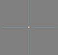 MODELER, PRESSING 'SPACEBAR' TO COMPLETE AN OPERATION Once you have achieved a proper placement, press the spacebar to complete the point and the cyan crosshairs will disappear. The point will solidify. Until you press the spacebar, the point is not in your 3D world. After you've set the point, if you don't see the point in a particular View, that view probably isn't of the 'Wireframe' type. Turn that View to 'Wireframe' and you should see your point (if it is within the field of view, that is). MODELER, ONLY POLYGONS RENDER Since points don't render, it matters nothing what size they appear to be on the screen. You might say that just as in mathematics a point has no size at all. Only polygons render. IMPORTANT POINT - "Unconnected points do not appear in a final rendering unless they form completed polygons." If the points are too small for you to see, at any time you can make their apparent size bigger. To change the apparent size of points, go to the Display Options Panel by pressing 'd' and select the 'Interface' tab.  MODELER, CHANGING VISIBLE POINT SIZE Checkmark 'Simple Wireframe Points' and click the 'Point Size (Pixels)' box, type a number such as 4.0, and click the OK button. You can also place down points by repeatedly clicking the right mouse button to place each point. In this case, you would move the points one-by-one to their proper places after they've been laid down. It is really more of a matter of choice which way a person decides to place and position points. MODELER, THE CURSOR'S YOUR FRIEND Now's a good time to mention the cursor. LightWave's cursor is always changing shape to tell you what mode you are currently in. It is a good thing to become aware of what the cursor looks like at any moment because you can tell what you can do and not do by which cursor is currently on the screen. For example... Down at the bottom of your screen are two buttons called Points and Polygons. When you're in the Points mode (meaning that lightwave will display points to you, rather than polygons) and YOU DON'T CURRENTLY HAVE A TOOL SELECTED, you will get a horizontal/vertical crosshairs for a cursor.  This is what the Points button looks like if selected... Note that you can enter either Points or Polygons mode by pressing CTRL-G for points or CTRL-H for polygons.  MODELER, MOVING POINTS AROUND After a point has been laid down, you can move it around in your 3D world. Notice that the points you laid down with the point tool are 'selected', (a yellow color). You can move a selected point by going to the 'Modify' tab and clicking 'Drag' or by pressing CTRL-T. Since you will proably be using this alot, it is best to remember the keyboard combination. The cursor for the Drag tool is a double-vertical/horizontal line crosshairs. It is best to get used to this cursor as you'll probably be using it a lot.   MODELER, deselectING ALL POINTS To deselect all points, so that the drag tool can be used on all points in your 3D world instead of just the selected points, NO TOOL CAN CURRENTLY BE SELECTED SUCH AS THE DRAG TOOL. Press the spacebar to unchoose the Drag tool if it is selected. The cursor should again show the horizontal/vertical crosshairs of the Points mode if the 'Points' button is depressed. Now, you can deselect all points. There are two ways of doing it... The easiest is to press the '/' key, or you can click the Points button, clicking in the empty box that's to the right of where it says 'Sel: 4' and the number will go to 'Sel: 0' and all points will become deselected. If, at this point, all of your points seem to have disappeared, then the type of View is not set to Wireframe, but some other type such as 'Smooth Shade'. Set the View type back to Wireframe for some View and you should see all deselected points. MODELER, HOW TO SELECT AND DESELECT POINTS To select any point if no points have ever yet been selected and while the 'Points' button is highlit, just click on a point. If you don't release the mouse button, you can keep selecting more and more points by just dragging the mouse over them. The instant you release the mouse button, from that point on, no deselected points will become selected. Click the mouse and hold the button down and drag the mouse over already selected points and they will become deselected. As long as you keep the mouse button depressed, you can continue dragging over more selected points and they will become deselected. This mode toggles. At all times you are either in one or the other of the modes. If you have your finger off the mouse button you can defintely say that you can either deselect points or you can select points one after the other by holding the mouse button down and dragging over points. MODELER, AM I IN 'SELECT POINTS', OR 'DESELECT POINTS' MODE? How can you tell which mode you're in at any time? Well, click and hold the mouse button down and roll it over a selected point and if it deselects, you're in 'Deselect Points' mode. At first, the mind thinks it should work some different way. But, as you begin to understand the process, it's a quite easy thing to learn. If you run into problems, you probably have a tool selected. Try looking at your cursor and making sure you see the horizontal/vertical crosshair cursor that tells you that you are in Points mode without a tool selected. MODELER, 'SELECT POINTS' MODE If you have points highlit, and you wish to enter the 'highlight more points' mode, just hold down the SHIFT key, hold down the mouse button, keeping it held down, and drag over deselected points and they'll become highlit. And, after points are highlit, after you've released the mouse button it is always in the mode where you hold the mouse button down and run it over points and they become deselected. Pretty simple after you get used to it. That's all there is to it. If at any time you get confused... Just start over again by making sure that no tool is selected by pressing the spacebar, and pressing '/' key to deselect them all. Start selecting them again. If you accidently ever have it change to Polygon or Volume modes, realize that all points that you selected will be remembered. The next time you click the Points button, you'll suddenly see the points you already had highlit. So, if all of a sudden all your points seem to have disappeared, check the buttons at the bottom to make sure that it says 'Points' as it is not easy to have it unhighlight all the points you have highlit. You must go through that strange 'Click the Points button, clicking the empty box to the right of the 'Set: #' box or press the '/' key when no tool is selected. Neither of these things is an intuitive or easily remembered thing to do if someone hadn't told you (Is this an ignorant attempt by NewTek to keep those who didn't buy the program from using it?). MODELER, CYCLING POINTS/POLYGONS/VOLUME BUTTONS WITH SPACE BAR When no tool is currently chosen, you can have it cycle through the different modes from Points to Polygons to Volume button and back to Points by pressing the SPACE bar. This was a stupid thing for the company to do, for space bar already has a purpose and sometimes those purposes get crossed. It is easy to get confused as to what one is doing. Lets say that points won't highlight as you think they should, so you suddenly think that you must have some tool like the DRAW tool chosen, so you press the SPACE bar because you remembered me saying that SPACE bar unchooses all tools which currently may be chosen. But, in reality all tools were ALREADY UNCHOSEN... Therefore, the program doesn't unchoose a tool. Instead, it flips you from Points to Polygon mode. All the points you had selected go dark, so you think you just lost all the work you did highlighting points. All of a sudden, the points are no longer highlit and you don't know why. If this ever happens to you, first check that the Points button is in the proper mode (or Polygons' if you're in that mode). MODELER, TURNING POINTS INTO POLYGONS Up until now, you have not created any shape which could be seen as a 3D 'object' because LightWave never renders just points. It is only when points are connected together to form what are called 'Polygons' that they can 'render' (be turned into a 3D object). When you combine points together with lines between them, and they form 2-dimensional shapes such as triangles, rectangles, or any other multi-sided shape - these are called 'Polygons'. So, first make sure you're in Points mode with no tool chosen. MODELER, NOW IT'S YOUR TURN Lets start off with a clean slate. Go to the 'File' menu and do 'Close All Objects' to wipe everything clean. Randomly place 20 points with the Point tool in the 'Back' View by clicking with the right mouse button. You should see the points as you lay each of them down. All of the points should be selected when you're done. It doesn't matter where you place them in the view. They will look something like this... 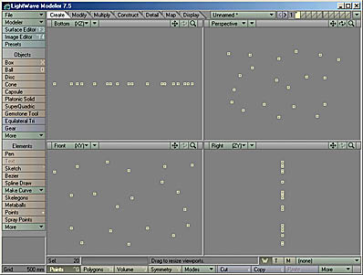 MODELER, DESELECTING ALL POINTS Press the spacebar to unchoose the Point tool and select the Points button (or press CTRL-G). deselect all of the points by pressing the '/' key or by clicking the 'Points' button, clicking in the empty box to the right of where it says 'Sel: 20'. All the points should turn white (be deselected), and it should say 'Sel: 0'. Make sure that the upper-right Perspective View is set to the 'Wireframe Shade' view type. Make sure the Top, Back and Right views are in 'Wireframe' type. MODELER, CONVERTING POINTS TO POLYGONS Now, beginning somewhere, start selecting points that form rough rectangles in the random pattern. And, the order that you select those points is important. I have numbered these four points in the order I selected them. LightWave remembers the order that you select points in, and once you tell it to create a polygon, it will follow the dots just like on those old numbered follow-the-dot games of childhood. Note that the upper-right window may be a little different. LightWave remembers the last angle that you were in in that window, and therefore it may be twisted in some different direction from the direction mine is in. It should now look something like this:  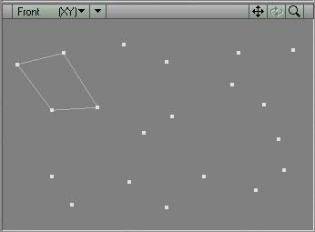 Continue connecting four points at a time, pressing 'p' after each set of four points, until all of the points have been turned into four-sided polygons. I generally go clockwise with each set of four points to ensure that I don't mess up the order of placement of the points. After you're done, it should look something like this: 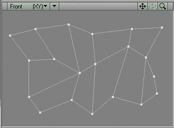 MODELER, VIEWING POLYGONS IN PERSPECTIVE VIEWPORT Now is the time to see your polygons. Go to the 'Perspective' viewport and hold down the ALT key (or the equivalent that you've figured out on your computer). Click the mouse's left mouse button, dragging the mouse back and forth. The image in the perspective windows should rotate. Sometimes it is handy to have one view be bigger than the other three so you can work in that view better. Move your mouse to the center of where the four views intersect and your mouse cursor should turn to four arrows in four directions like this:  MODELER, INCREASE SIZE OF ONE VIEWPORT In this case, you want the perspective view to be bigger than the other three views, so while the cursor looks like four arrows, click with the left mouse button and drag down and to the left with your mouse. The perspective window should grow in size while the other three view windows shrink to compensate. This will only work if you have your monitor set to a large resolution (above 1024 x 768). If you have a lower resolution monitor, you can turn the whole view area into just one view by pressing 'd' key and selecting 'Single' where it has the 'Layout:' drop-down menu on the Layout tab. Select 'Perspective' as the one view type from the drop-down menu at the upper-left of the view. MODELER, ZOOMING IN AND OUT IN A VIEWPORT After resizing the Perspective View, press the '.' key (greater than) to make the flat polygon array bigger and ',' key to make it smaller, and pointing with the mouse and 'g' to rearrange the position of the array. After rotating your flat object, you should notice that one of the two sides of your flat object is a light gray color, while the other side is the same color as the background. Turn the object so that the light-gray side is towards you. It should look something like this: 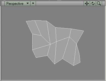 MODELER, SELECTING POLYGONS You can select polygons in much the same way as you can select points. This time, click the 'Polygons' button at the lower left of your screen, or press CTRL-H. Just as with Points, if it ever says some number other than zero to the right of the Sel: box, some polygons are already selected. You can deselect polygons by just clicking selected polygons (just as with points in Points mode). MODELER, DESELECTING ALL POLYGONS You can deselect all polygons by clicking the Polygons button, clicking the empty box to the right of the Sel: box (just as with Points button). MODELER, SELECTING MORE POLYGONS You can select more polygons by pressing the Shift key, selecting more polygons. For a moment, change the View type to Wireframe instead of 'Wireframe Shade'. Now try shift-clicking a polygon. It won't highlight because in Wireframe mode, there is no surface to a polygon. That can be helpful. To highlight a polygon in Wireframe mode, you will need to highlight any polygon's EDGE line rather than the center surface of a polygon. IMPORTANT POINT - With the Wireframe View Type, you must select a polygon by selecting an edge of that polygon, not the center of it as you can with a view type like 'Wireframe Shade' which shows you the surface of the polygon as well as the connecting lines between the points. MODELER, SELECT POLYGONS ON OTHER SIDE OF OBJECT This means that when you are in the 'Wireframe' view type, you can select polygons on the 'other side' of an object, however. In 'Wireframe Shade' view type, you can only select polygons on 'your side' of the object, having to turn the object around to highlight polygons on the other side. Therefore, in the 'Wireframe' view type, if two polygons share a joined line, both polygons will be selected, and you'll have to deselect one of the two polygons that just became selected. You should get used to selecting polygons and deselecting them because much of working with 3D objects deals with the selecting and deselecting of polygons and points. Again select the 'Wireframe Shade' view type in the Perspective View. I have taken you to the 'Perspective' view because I want to now show you how powerful this view is. You can warp these flat polygons from this view. MODELER, ALT + MOUSE BUTTON ROTATES WORLD IN PERSPECTIVE VIEW Press the ALT key and click in the perspective window, dragging the flat polygon array up and around so they are at an angle like this to you... 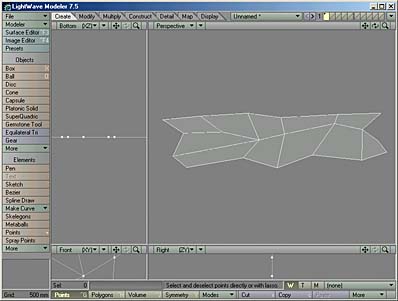 Click the Polygons button or press CTRL-H. The cursor that indicates that you are in polygon mode with no tools currently chosen is a diagonal crosshair.  Make sure that it says Sel: 0 (no polygons selected). DRAG TOOL Press CTRL-T or select the Drag tool from the Modify tab's button choices. You should see this cursor: MODELER, DRAGGING POINTS Dragging points that are connected together is the same as dragging points which aren't. You will be dragging the points which connect together the polygons, but this time you won't be dragging them from the three separated views, but only from the perspective view. Try dragging one of the points of one of the center polygons upward (a point which has four lines connected to it). You should see all four connecting lines warp upwards, following the dragged point. When no points are selected, the drag tools will work on all points. The drag tool ONLY works on points, not on polygons. Try moving a second point upwards. Now, rotate the object and see that the two points 'stick out' from the flat surface now. MODELER, MOVING POLYGONS (You could use the 'Move Tool' to move a whole polygon, not disturbing any of the four corner points, by first selecting that polygon, entering the Move Tool by going to the Modify tab and picking the Move button, or by pressing the 't' key without pressing the CTRL key at all). This method of 'Press ALT key, rotate object in Perspective View, let up from ALT key, drag upward on point with drag tool, 'Press ALT key', click in perspective window while holding down the left mouse button, dragging the object to a new angle, letting up on the ALT key and mouse button, pointing to a point, dragging that point to a slightly new position is basically it. If that were all you learned, you could build anything. Just with what I have just taught you, you just need to know one more secret before you start building rocketships, people, dinosaurs, cartoons. I have warped a few points in my polygon array up and down and this is what I end up with, which looks like a very simple mountainscape. You might say 'so what?', but I say there is the beginning of a woman's body.  MODELER, THE 'SUBSURFACING' MODE The 'Subsurfacing mode' is amazingly simple. It just means, "Press the TAB key to turn it on, press it again to turn it off." However, the most difficult thing about the Subsurface mode is that you need to do it over the entire surface of your object, not just a part of your object. If you have any polygons selected when you press TAB, those polygons will be the ones that will become subsurfaced, not the whole object. So, if you have a nicely warped array of polygons... lets get to it. Disengage the Draw tool by pressing the spacebar and again press the Polygons button and make sure it says Sel: 0 If it doesn't, you know the drill. Turn off all the polygons. After they're all deselected, press the TAB key. The sharp angular surface has disappeared and a nice smooth surface has appeared. My mountainscape now looks like this: 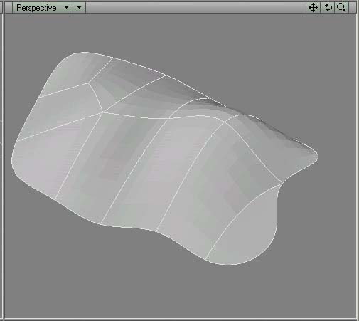 MODELER, TURNING OFF THE CAGES When in subsurface mode, sometimes it is helpful to turn off what are called the 'Cages'. I always like working with the cages turned off. so in my picture the cages are turned off. Let me go to the Display Options Panel by pressing the 'd' key and turn it back on again. And, now, you should see the cages (which basically just means, 'The polygons if subsurfacing mode was not turned on'). 
Again enter the Draw tool by pressing CTRL-T and now try moving the points again. You can either move the point at the end of the cyan cages, or you can move the point where the subsurface lines intersect. IMPORTANT POINT - ":Most of the time, it is best to stick with four-sided polygons." LightWave's subsurface mode always does best with four-sided polygons. Three-sided polygons are used when an area must bend without extreme warping but you will not get a beautiful smooth surface with triangles. MODELER, FIVE VERTICES RATHER THAN FOUR And, when you have places where five Vertices all intersect (which is sometimes necessary in order to join together intricate surfaces) you will oftentimes get a visible pucker in your rendered object. Therefore, you should always try to plan your object so that it has only four-sided polygons in it. If you can do that, your object will always be perfectly smooth (particularly when you go to Subsurface mode, which I'll be describing in the future). As a rule of thumb and if at all possible, except in areas such as the elbow which needs to bend -where you might choose to split the rectangles in half to form triangles so they will bend easier, or a complex area such as the breast/chest/armpit region of a body stick with four-sided polygons. And, if you do need to use 5 sided polygons, try absolutely never to use six or more. The puckering gets worse and worse as the number of sides goes up. Every five-sided polygon you make will always create at least one 5-or-more-pointed Vertex somewhere. MODELER, THE 'OTHER' WAY OF CREATING ROUNDED POLYGONS A less computer-intensive method of creating rounded objects has to do with 'smoothing' a surface. You won't get half-as impressive objects by doing it that way, but if you have a slow computer, it is the only way to do it. Back up one step by making sure that all polygons are not selected, pressing the TAB key to get it looking like this again... Next, enter the polygon mode by pressing the Polygons button and this time, use the right mouse button instead of the left, dragging a line around the polygons in your array.  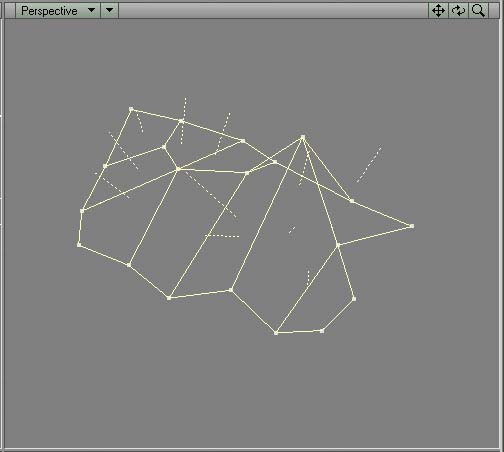 MODELER, THE 'CHANGE SURFACE' CREATES SURFACE NAME Press the 'q' key to bring up the 'Change Surface' panel and give it the name 'Array'. Also, while you're here, click the square just to the right of where it has Red, Green, Blue and change the color of those polygons to white (or whatever color you'd like). And, here's the second secret, checkmark 'Smoothing'. 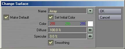 This is the way that you name selected polygons so that you can change those polygon's surface texture, make it look like a mirror, or change the color. Although changing the color to white won't seem to do much in modeler, when you actually light it and render it over in Layout, the surface will be white. Deselect all polygons and you're left with a more-rounded surface on your sharp polygon array. The peaks are just as pointed as they were before, though. So, you need many more polygons in order to create a rounded surface, particularly at the edges, than you do when you're using 'Subsurface' mode. 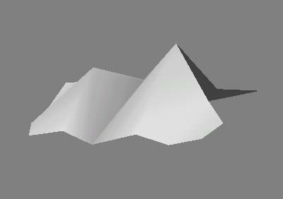 MODELER, THE OLD WORLD OF POLYGONS Just know that this is the way that it used to ALWAYS be done. Before what was called 'B-Splines', and later MetaNURBs, and now 'Subsurfacing', this is the way that you would have created organic objects like bodies. People oftentimes utilized textures to mask this jaggedness and give the object more of a sense of reality. But, you don't have to do that any more because I just let the cat out of the bag. It's best to name your whole surface and turn smoothing mode 'On' even when you're using Subsurfacing anyway. Otherwise, the pre-rendered objects in LightWave Layout will look polygons rather than a smooth surface. I believe the finished rendering is also smoother. It's best to name surfaces as you build them, such as 'arm', 'leg' 'nose', 'breasts', 'nipples' and such. Particularly if you think you're going to want to change the color or texture of those polygons separate from other polygons later (such as lips, or nipples). So, that finishes the tutorial on Points and Polygons. |
||
