
|
|
||
|
8. Creating Objects from Front/Back Images |
||
 MODELER, CREATING A WEST MEXICAN SHAFT TOMB FIGURINE Next, I will create a figurine object using the Front/Back images that I digitized in Tutorial #7. WARNING - The last tutorial was talking about Photoshop when it mentioned keyboard shortcuts or menus. This tutorial will refer to LightWave keyboard shortcuts and menus unless it tells you otherwise. MODELER, CREATING A BOX THE SIZE OF THE FIGURINE I open the Modeler program. Next, I have to figure what the aspect ratio (height to width ratio) is on my figurine because I will have to create a box that is the same aspect ratio as the front.bmp and back.bmp images in order for the Automatic Size to work properly. A good size to do it is 10" high by 8" wide at 72 dots per inch. Pick 1024 as the Image Resolution. A BMP file of this size should be around 500K in size. If it was ten times that number of inches, the size of the file would be 53 megabytes, which would be 100 times the size of the file, so be careful of creating a BMP much over 1 Meg in size. As for the aspect ratio of the box to make... I look under Images->Image Size in Photoshop and it says 4.375 inches wide x 8" tall at 72 dots-per-inch. In LightWave, one meter tall would be a good size. So, I can now make a ratio. 8 inches is to 1 meter as 4.375 inches is to x meters. That turns into 8x = 4.375 or x = (4.375 / 8) meters = .547 meters or 547 milimeters. Thus, in LightWave I go to the 'Back' viewport, press SHIFT-X to bring up the 'Box' mode, press 'n' key to bring up the Numeric Requester and enter .547 m for Width and 1 m as Height. I make sure that Center X, Y and Z are all 0 m and click the requester's close gadget. I press the right-hand ENTER key to set the box and the box turns from cyan to white with four white dots at each corner. I enter the Polygon mode, select the square, pressing 'd' to bring up the Display Options panel. I pick the 'Backdrop' tab, select BL (Bottom Left Viewport), Select 'load image' from the 'Image' drop-down menu, select the Front.bmp file and it should appear. I click 'Automatic Size' and 'Fixed Aspect Ratio' unchecks but Automatic Size box now says 547 mm, and click 1024 as Image Resolution for best quality. Press the '.' key (un-shifted greater-than key) as many times as necessary to increase the size of the backdrop image if it is too small in the viewport. MODELER, LAYING DOWN INITIAL KEY POINTS Press the '+' key on the numeric keypad or select the 'Points' button under the Create tab and right-click in each red circle, being careful that the point is tangent to the edge of the object. Do this with all the red dots. 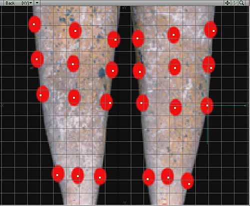 First, unselect all points by entering Points mode (SHIFT-CTRL-G or down at the bottom left of the LightWave window). Click in the empty box to the right of where it says Sel: and the number of points selected should go to zero. If you had 'Smooth Shade' view type set in the 'Back' viewport, setting it to 'Wireframe' view type or you won't see any points. MODELER, CONNECTING POINTS TOGETHER INTO FOUR-SIDED POLYGONS Select each four-sided polygon in a circle. You can select them either clockwise, or counter-clockwise, but do it in a circle, one after the other. Remember when selecting points, select the first point with the left mouse button and KEEP THE BUTTON PRESSED. Move the mouse with the button pressed and cross over the second, third, and fourth points. If at any time you lift up on the mouse button, press SHIFT and click the next sequential point until you are done. After you have done four points, press 'p' to make the polygon. Remember to always make 4-sided polygons and don't think you have to stick to the red dots, they were just put there so it would be an easier task when you did the points. Note that I had to change the point positions in a couple places outside the range of the red dots I had placed earlier. 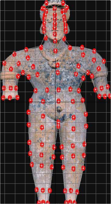 MODELER, ADMIRING YOUR CREATION Once you think you have completed all of the polygons, go to the perspective window and choose the 'Wireframe Shade' view type. This will allow you to see both the polygons, and which side of the polygon is shaded. You should see a randomly scattered set of polygons, some gray and some transparent. 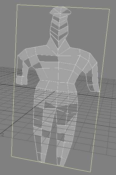 Make sure that just the rectangle is the selected polygon like you see in the following image, pressing 'x' key to cut it to the clipboard (make sure that the Caps Lock key is not turned on). The rectangle should disappear from Layer 1. Select the second Layer by clicking the top half of the second layer gadget  , and paste the rectangle into the second layer with the 'v' key. , and paste the rectangle into the second layer with the 'v' key.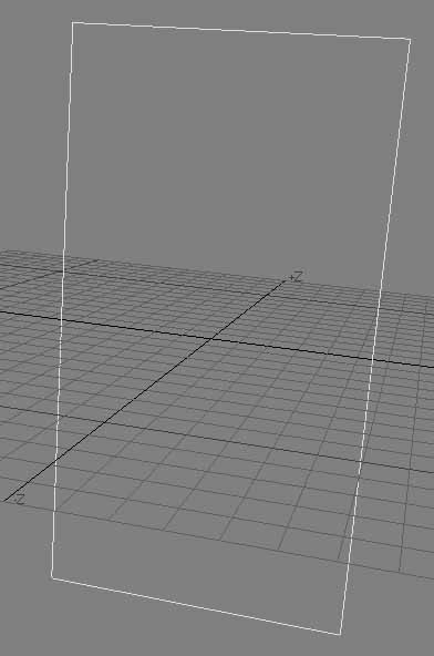  , and the figure polygons should reappear. , and the figure polygons should reappear.MODELER, FLIPPING BACKWARDS POLYGONS You need to flip all polygons which are backward in the figurine. Go to the 'Back' viewport, and select the 'Wireframe Shade' view type. You will see some polygons turn gray. Select all polygons that are invisible by first turning off all polygons by clicking the Polygons button or pressing CTRL-SHIFT-h, clicking the empty box to the right of the Sel: box and all polygons will turn off. Select the first transparent polygon, holding the shift key down and click each other transparent polygon until they are all selected. Press 'f' to flip those invible polygons. They should all become gray. If not, you probably missed making a polygon. 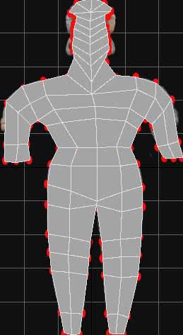 MODELER, POLYGONS YOU MISSED CREATING If a polygon does nothing when you try selecting that polygon, yet you know that the lines around it are highlit, you possibly missed making those points into a polygon. It possibly is just points. All of the polygons around that polygon are turned on, the problem is almost definitely that that polygon was never created. I save the LightWave object as 'Figure 1.lwo'. Turn off all polygons. In the 'Back' viewport, highlight one polygon and press the ']' key to highlight all connected polygons. This ensures that all polygons are now selected. 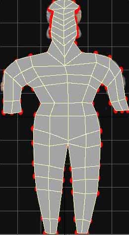 MODELER, CLONING THE FIGURINE'S FRONT TO MAKE THE BACK Make sure your Caps Lock key is not turned on, right-click in the 'Right' viewport so you don't disturb any of the polygons that are currently selected, press 'c' key to copy all polygons to the clipboard. Press 'v' key to paste another copy of those polygons. No observable difference will occur. However, press 't' to turn on 'Move', tjem n' to bring up the 'Numeric requester. Type 200 mm as the Z offset and click 'Apply'. You should now see a second set of polygons to the right of the first set. 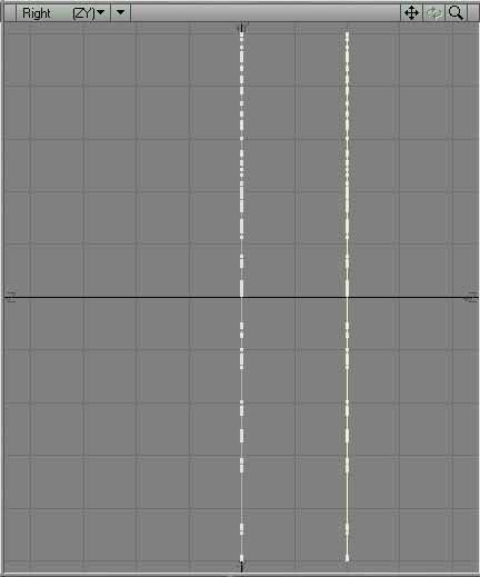 Go to the perspective viewport and press the ALT Key as you click in the window with your left mouse button and drag. This will rotate the world. Turn it until you can see the side of the polygons which are shaded. 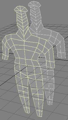 MODELER, FLIP EVERY BACK POLYGON TO POINT BACKWARDS One set of the two sets of polygons will be on the 'inside' of the figure. Unselect all polygons, select one of the polygons of the set that is inside-out, and press ']' to select all connected polygons to that polygon. Press the 'f' key to flip all of those polygons. They should look invisible. 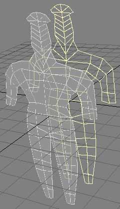 Go to the 'Perpective' viewport, press the ALT key, making sure the Grid is turned on (press 'd' key to turn it on) so you can see the +X, -X, +Z, -Z indicators. Rotate the world with your mouse until you can see which set of polygons are the 'front' ones (remembering that we have our figure turned backwards. The 'Front' of the figure is currently on the X axis, and the 'Back' of the figure is offset in the +Z direction. In the case of this image, the selected polygons are the 'Front' polygons. 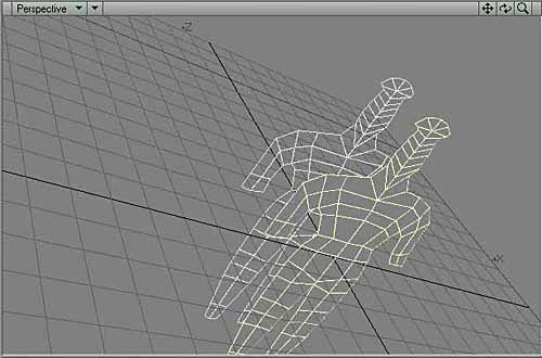 MODELER, NAMING THE FRONT AND BACK POLYGON SURFACES With all of the front polygons selected, you must now name that as a surface. Press 'q' to bring up the 'Change Surface' panel. Type in 'FrontPolygons' and click 'OK'. 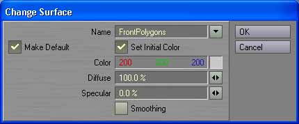  MODELER, CREATING THE FIGURINE'S SIDES Select all points that are around the borders of both polygons without selecting any points within the surfaces. The best way to do this is to go to the 'Back' viewport and choose the 'Wireframe' view type. If you have 'Wireframe Shade', the front surface may block you from selecting back points. After you think you've selected all of the outside points, rotate the two sets of polygons in the 'Perspective' view to make sure. Follow each outside row with magnification turned on until you have verified each set of points are unbroken all the way around each set of polygons. 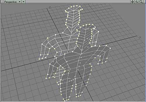 This will bring all of those points together, halfway between the 0 Z axis polygon set and the 200 mm polygon set. The points will NOT be automatically welded together though. They will just be in the exact same locations in the 3D world.  MODELER, WELDING THE PERIPHERAL POINTS Now, you must weld each of those pairs of dots together, a pair at a time. Deselect all points by doing CTRL-SHIFT-G, clicking in the box to the right of Sel: Start at some knowable set of two points, like the bottom left set of two points (will look like just one point). Make sure that you have 'Wireframe' view type chosen in the 'Back' viewport. Select the point at the lower-left leg and rub back and forth a little with your mouse's left mouse button held down to ensure that both points of the point set are selected. Press 'CTRL-w' to weld them together. If you succeeded in selecting both points, it will say:   After you have welded two points together, and after you click the 'OK' button, the point that was welded will become un-selected, so make sure you watch to see the last one you did or you will lose track of where you are. MODELER, SUBSURFACING MODE Make sure that all polygons are turned off. See that it is in 'Polygon Select' Mode by pressing CTRL-h. Press the TAB key and it will go into subsurfacing mode. Because of the nature of subsurfacing mode, the figure will become thinner. 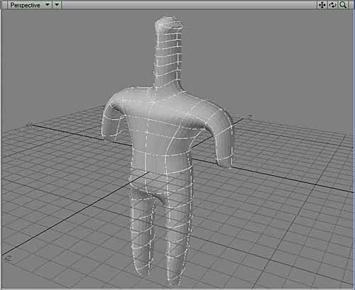 Expand the 'Back' view by moving the center cross between the four views with your mouse up and to the right. Turn off the grid by pressing 'd' (Display Options), unchecking 'Show Grid'. This will make things less neurotic. Turn on 'Show Cages' - Cyan cages will appear. Click 'OK'. 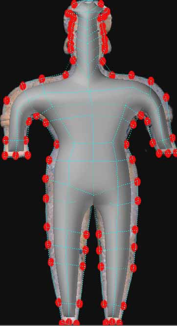 MODELER, STRETCH THE SUBSURFACE BOUNDARY LINES Magnify the 'Back' viewport so you can see the backdrop picture's edge, press CTRL-t to enter the 'Drag' mode, and drag each edge guide to line up with the edge of the image. At any time, if there are points that are outside the viewport area, you can point to a position in the viewport window and press the 'g' key to 'go' to that point (it puts the place you point to in the center of the viewport). 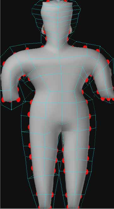 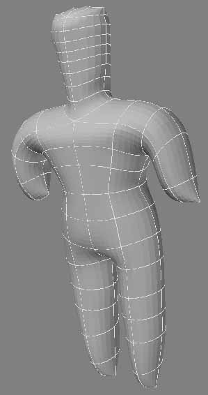 In this case, there are eight in the body, but only four around the head. Four makes a round object look pointy when you're in subsurface mode. But, at least the body has the potential of looking good, so I now will work in the Perspective window for a while. MODELER, ORIENTING YOURSELF First, I will have to orient myself in the Perspective window again as I've rotated it so much I have no idea which is front and which is back. To orient myself this time, though, I will go to the 'Right' viewport. I know that the left side is the 'Front' of our object (what LightWave would call the 'Back'). So, if I highlight the leftmost polygons, I can be sure that those polygons are on the side which would have my figure's face on it. The rightmost polygons in the 'Right' viewport would be the side where my figure's ass would be.  In this image, the yellow polygons are my figure's 'chest'. This is because I am creating the figure backwards in the 3D world. If this still confuses you, don't feel bad. You'll get used to it eventually. MODELER, ACTUAL MODELING There is always that time period where you are laying down the polygons. Until they are there, you can't model them. But, there's always that time that comes when you have enough polygons laid down to start forming and shaping them. I will now start modeling. I would call all that other stuff preparation for modeling. I oftentimes will throw an object into a really steep angle when I'm readjusting the position of surface points. That way, I can see it like one might drive on a roadway. It emphasizes the symetry, and lets you separate the polygons from each other better. So, here, I would go to the Perpective viewport, hold down the ALT key, and rotate with my mouse until it the figure was lying down (making sure, at first, that the ass side is up. That way I can be sure of which side I am looking at from then on. Can't mistake the ass). 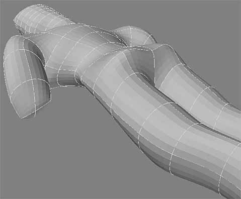 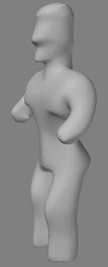 |
||
