
I got in a deal for a one-off exhaust flange, dig on it.
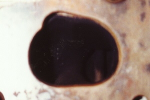
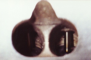
To the left is the exhaust side of the engine, the driver's side on a RWD car, the front of a FWD car. The new exhaust flange I got (Thanks, Bruce) is bolted on and ready for tubing and the turbo flange. It was cut with a waterjet, or a very high pressure "beam" of water that cuts just like a laser, but is much cheaper in operation. The right hand picture is the intake side. Below are close ups of the exhaust port and intake port, respectively. Notice both are siamesed and are narrower as they get closer to the face of the head.
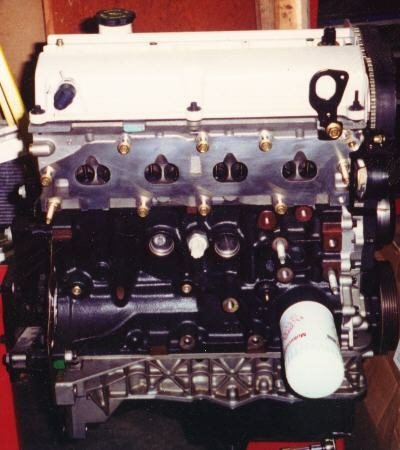
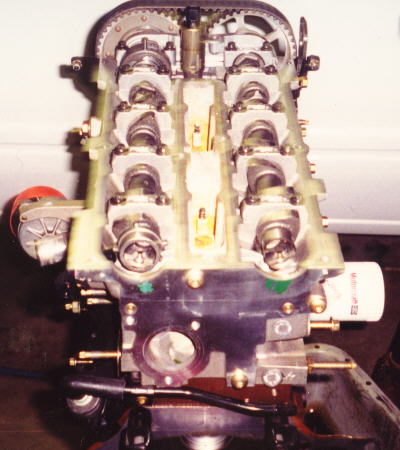
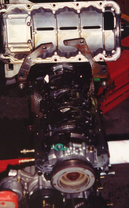
Also of interest is the secondary aluminum webbing below the crank centerline, and the separate oil sump. This improves the Zetec's bottom end strength, reducing block flex and noise in general.
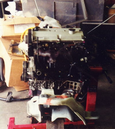
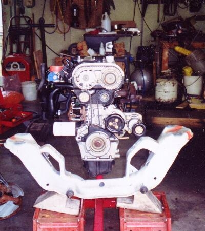
This is the '98 GT k-member and what it will look like when in the car.
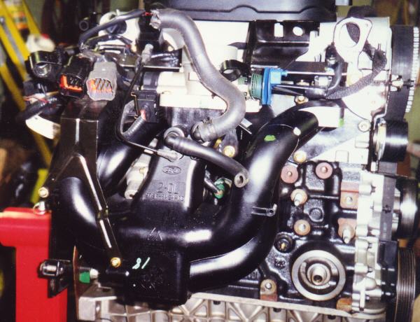
This is a shot of the intake (passenger side of a RWD, rear on a FWD). It's an ugly little beast full of 90°(+) bends, and it has no place on a turbo engine, so that was the last time it will ever be mated with the head, functionally. The dual overhead cams will aid significantly in power production with the turbo. The Zetec has a Variable Cam Timing system that I may will eliminate, it's a part of the emissions system on this particular model. Adjustable cam gears will take the place of the stock gears.
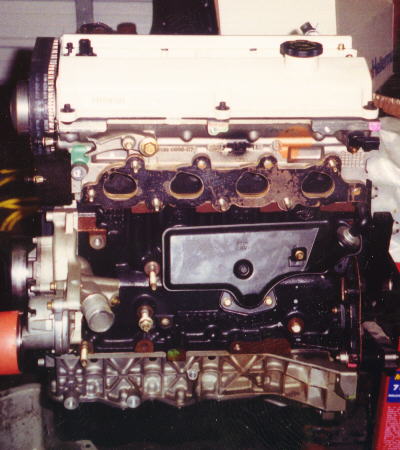
To the left is the head with cam cover removed. The left hand cog/cam is the exhaust cam with the VCT servo on the front (top of picture) of the cam, and the cam position sensor at the rear of the engine on the very end of the cam. Below the exhaust cam is where the coolant manifold/thermostat housing bolts. This is going to be an interesting part of my project because the housing is going to be very close to the firewall of a Mustang, so I may have to mount the engine forward of the transmission's stock mounting position. I will probably end up cutting into the firewall to put the engine further back than the 2.3 so as to get the engine behind the K-member and front axle centerline.
To the right is the bottom end of the engine. The aluminum secondary support is what is on top of the picture. It is oriented left side to the rear of the engine (where the transmission mounts, the crankshaft pully is at the bottom of the picture). This secondary webbing has a cast-in windage tray, which gives the block more strength, reduces oil foaming, keeps oil off the crankshaft, and prevents oil from sloshing as well as keeping noise low.
 Back
Back
