
Figure 9.1 Paper capacitors in a radio chassis.
Chapter 9 Antique Equipment.
9.1 Before Turning on the Power.
9.2 Pre 1930 Radios.
9.3 Pre World War Two Radios.
9.4 The All American Five.
9.5 Three Way Portable Radios.
9.6 Phonographs and Record Changers.
9.7 Consoles and High Fi Components.
9.8 Wire and Tape Recorders.
9.9 Why TV Sets Are Not covered.
Chapter 9.
Antique Equipment.
Many items of tube equipment are more than 50 years old which qualifies them as antiques. If one of these items turns up on your service bench how it is treated depends on whether it has not been turned on for several decades or if it was in daily use and suddenly failed to operate. The former case is covered in This chapter.When such an item is brought to your shop by a tearful owner who states that he or she used to listen to it at age six and asks you if you can make it work again even though it may have been stored in a damp basement or hot attic for the last 50 years you are definitely on the hot seat. Such an item requires special care.
There are many special procedures which must be followed if the item is ever to function again. Failure to observe even one of these procedures may result in serious damage to the equipment that may be difficult or even impossible to repair.
One of the many things that is unique about servicing antique equipment is that except for common parts such as tubes, resistors, and capacitors, many of the parts are simply no longer available at any price. Great care must be taken to avoid either physical or electrical damage to these parts.
Authentic Parts Versus Modern Parts.
Some restorers are nuts, that's right I said nuts, over keeping the inside of their radios authentic looking. How many people are going to be interested in looking inside a radio. OK, other restorers. If you are fixing up a radio for competition you will need to be nuts. But most of us just want the radio we found on eBay that is the same make and model on which we used to listen to The Lone Ranger to work and we don't care if it has dog bone resistors and capacitors that look like they are wax paper even if they are plastic on the inside.In the final analysis you have to decide just how authentic you want your treasured radio to be.
If you are doing the restoration for someone else you must be sure that you and the owner are in agreement about the degree of authenticity. Be sure that the owner understands that as the radio becomes more authentic that the bill will rise. Failure to communicate may result in you having a very authentic radio on your hands with hundreds of dollars of your own money wrapped up in it with no way to recoup your losses.
Authenticity Versus Safety.
In this area I am absolutely adamant. Safety always trumps authenticity when ever and where ever they come into conflict. The example that is most often sited is the All American Five radio. There were millions of these produced in the years roughly between 1945 and 1965 and there are still hundreds of thousands still in existence and in more or less working order.Their danger comes from the fact that the chassis is connected to one side of the power line through the off/on switch. You may find that the chassis of the radio has 120 volts between it and an earth ground such as the kitchen sink. I hope you didn't find this out the hard way. So you do the logical thing and reverse the plug in the socket. All is fine until you turn the radio off. Then you find that there are 120 volts between the radio chassis and ground. That's right, you can't win. The chassis is "hot" no matter which way the plug is inserted in the socket. Detailed rewiring instructions with diagrams will be given in the section on post WW II radios. This is one area in which authenticity MUST be sacrificed for safety's sake.
For additional information on tube amplifier and radio circuits see The Fun with Tubes website. Also see Electronics for Physicists particularly chapter 4A.
Back to Fun with Transistors.
Back to Fun with Tubes.
Back to Table of Contents.
Back to top.
9.1 Before Turning on the Power.
There are certain dos and don'ts that should be observed when working on any piece of antique equipment. They are as follows.1. Don't plug it in and turn it on.
2. Do replace paper and electrolytic capacitors and selenium rectifiers.
3. Do check all resistors for value and replace if more than 20% high or low.
4. Do check the power transformer by applying power with all tubes removed from sockets.
Replace Capacitors and Selenium Rectifiers.
The photographs below show examples of the capacitors that should be replaced.
Figure 9.1 Paper capacitors in a radio chassis.
These are wax paper capacitors. They are not just wax paper on the outside, they are wax paper on the inside as well. Refer to the construction of a capacitor in chapter 3. Instead of plastic film these capacitors use wax paper which is not unlike the stuff your mother used to wrap your school lunch sandwiches in. Paper is a hydroscopic material which means that it likes water. The wax is supposed to prevent the absorption of water but it won't work forever. Over time moisture in the air seeps into the capacitor and gets absorbed by the paper and its insulation property is compromised.Capacitors are supposed to be a totally open circuit for DC but a paper capacitor conducts some DC current. This is referred to as leakage current and a capacitor that conducts is said to be leaky.
When you find these capacitors in radios or other old equipment replace them with modern plastic film capacitors. Don't bother testing, don't turn it on to see if it will work, don't hesitate, don't ask, don't tell, just replace them.
The photo below shows some capacitors that look nice but they are wolves in sheep's clothing. Or paper capacitors in plastic clothing.
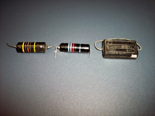
Figure 9.2a Black Beauty and Paper Capacitors.

Figure 9.2b Dark Red Mallory Paper Capacitor.
The one on the left in Figure 9.2a is a 47,000 pico farad, center is a 6800 pf and the one on the right is unknown. The 6800 pf is really blue, gray, red, but the blue and gray didn't translate well to the internet.The oddball on the right is disguised as a mica capacitor but it is nothing more than alternate stacks of foil and wax paper. True mica capacitors rarely have to be replaced but the paper ones are usually thicker than mica. True mica capacitors are not very thick.
The type of capacitor shown in Figure 9.2b is especially troublesome. In the mid 1960s, 50 years ago, I stocked up on these thinking they were good capacitors. They were at the time but time has been their enemy. They look really good. The ends of the plastic tube are filled with epoxy and they even test good on a digital RLC meter. The only clue that something is wrong is that the value reads out of tolerance high. I just finished going through them and they are 100% too leaky to be used in any circuit. Every last one out of more than 200 capacitors was bad and had to be thrown away.
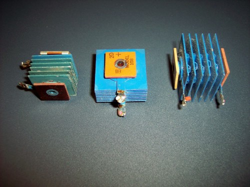
Figure 9.3 Selenium Rectifiers.
Something else that should be replaced before turning on the power are selenium rectifiers. Selenium dioxide is not just a bad smell it is a rather deadly poison in high concentrations. Replace them with silicon diodes and a series resistor. More about this when 3 way portables are covered. Use the rectifier's mounting screw to mount a terminal strip and solder the wires, the resistor and silicon diode to the terminals.Never, never, never, solder the diode across the terminals of the rectifier. It is going to short out some day and the results will certainly be catastrophic.
The section below was written by Mike (Mac) McCarty. Mac is a regular contributor to the Fun with Tubes email forum and Is highly knowledgeable in the areas of electricity, electronics, and mathematics. He has so many cogent thoughts on questions that are asked on the forum that I have prevailed on him to become a contributor to this book. I was going to write this section myself but when I remembered that Mac had written something along the same lines I read it over. I can't improve on what he said so why should I try to reinvent the wheel?
Mac is back on the fun with tubes forum after a long absents and his return is most welcome. He has written extensively on the subject of restoring antique electronics to operation and I recommend that you go there and read it over. Some of it is duplicated below but a lot more is material not found on this page.
I'm going to give you the instructions for locating the files before giving the link. Read the directions, then click the link.
The link will take you to the website of the "Vintage Radio and Phonograph Society". Once there click on the "Site Map" button.
Look down the list of links until you find "Technical Information Center". Click on it.
The two links of interest on this page are, "Introduction to Components by Mike McCarty" and "Introduction to Restoration by Mike McCarty". The first contains many photographs of old style components which you may have never seen before. The second is a much expanded and more detailed version of the section below. At the bottom of this page is a schematic diagram and parts list for the dim bulb tester. Now here is the link.
Vintage Radio and Phonograph Society
I now place you in Mac's capable hands.
Max Robinson.
Steps To First Power On.
by Mike (Mac) McCarty.
*** C A U T I O N ***
The high voltages associated with the older tube type equipment CAN KILL YOU!Before I get into trying to power up a piece of equipment (especially an old tube type) that hasn't been powered up in quite some time, let me say that I presume that the person performing these steps is aware of the dangers presented by high voltages, and is capable of using high voltage power supplies safely. If you have any doubts about your ability to take measurements of high voltages including AC line voltages, then do not perform these tests. Get someone else who is comfortable and experienced with high voltages to do them for you.
Disclaimer.
This little missive surely contains a mistake, or omission, or requires some other polishing. It is assumed that the reader has some electronic theory background. So use this guideline at your own risk. No one associated with the development of this document assumes any responsibility if you electrocute yourself, wife, cat, or dog.Introduction.
You've acquired a "new" piece of vintage equipment and want to restore it to service. What steps should you follow?There are several ways to power up a piece of equipment that hasn't been used in a long time.
- The quickest and most likely destructive way, is just to plug it in and turn it on. This can result in anything from a working unit, to blown fuses, or smoked parts. NOT a good method.
- Another method is to use a light bulb limiter. This does not allow high current, even if there is a short in the piece of equipment being powered up. The light bulb is in series with the piece of equipment under test. So if the equipment has a short, the only current that flows is that required to light the light bulb. For a 60 W 120 V bulb, that is 1/2 A.
A good rule of thumb is that a light bulb limiter allows a maximum of about 40 % of the lamp's rated power to be dissipated in the load.
For information on building a light bulb current limiter see:
Light Bulb Current Limiter.
Or Current Limiting with a Dim Bulb Tester.Though this method has much to recommend it over just plugging in the equipment, by itself it is not enough to ensure that the equipment does not get damaged.
- Another popular method is to use a variac to slowly bring the voltage up to "reform" the filter capacitors. Electrolytic capacitors have a tendency to lose their ability to store a charge if they have been lying around, not used, for a long time. I DO NOT RECOMMEND "bringing up voltage on a variac to reform capacitors". That is not a proper way to reform electrolytic capacitors.
Especially when the rectifiers are tubes, attempting to use that method can seriously shorten the lifetime of the rectifiers. Pulling current from the cathode of a rectifier running with reduced heater voltage can damage or destroy it.
Properly reforming electrolytic capacitors requires a current limited power supply, which a variac run through a transformer and rectifier is not. For more information on reforming electrolytic capacitors refer to Restoring Dead Capacitors.
This technique is superior to just plugging in the equipment, but it is also not enough by itself to prevent damage to the equipment.
- The recommended method takes a lot longer than the previous methods, but definitely reduces or limits the chances of doing any damage to the equipment. This requires disconnecting many parts of the equipment. Because of this, remember - the high voltages used in the old tube type equipment CAN KILL YOU. So proceed at your own risk.
Preparing to power vintage tube equipment for the first time.
Before beginning work on vintage equipment which has not been powered in some time, first remove all tubes, and mark them as to where they go. Sometimes "identical" tubes don't perform identically. If you remove an IF amplifier tube from an FM set, you may need to tweak alignment if you replace it with an "identical" but not the same tube.The heart of any piece of equipment is the power supply, and until the power supply is working properly and supplying proper voltages at adequate currents, one cannot hope to try to troubleshoot any of the other stages. Power supplies are like Mama. If Mama ain't happy, ain't nobody happy! So, I recommend you start with the power supply stage(s).
Preparing the Power Supply.
Power supplies often supply several different voltages at different currents. Usually, there are one or more heater or filament supplies which may be AC, and one or more high voltage DC supplies, usually called something like B+1, B+2, etc. Since a variety of voltages is supplied, and also to provide isolation from the AC line, such power supplies usually contain a transformer with separate windings for each heater or filament supply, and one or more high voltage windings, usually center tapped, with a rectifier followed by filtering stages, and sometimes voltage dividers, to supply the various B+ voltages.Many low end vintage radios have a so-called AC/DC power supply, that is a power supply without a transformer. If this is the case, then one may skip the steps necessary to test the transformer, and check the integrity of the insulation. Look down below to the section Testing the Input Side of the Power Supply. However, spend the time to read and understand the intervening sections, even if you are dealing with an AC/DC power supply, since the principles apply, and some of the techniques are used, in AC/DC supplies as well.
Otherwise, the first step in preparing the power supply is to test the transformer and ensure the power supply is safe to plug in.
Testing the Transformer.
This describes how to check a "characterized" transformer, one whose characteristics are known. Its behavior is characterized, it's a known item, or one which is installed into a piece of equipment which is characterized, and from which we can derive approximate characteristics for the transformer.If the transformer is "bare", we have no information about it other than perhaps some meaningless (to us) OEM part number, and it is "bare" in the sense of just the transformer, no equipment it is installed in, so we can't guess, except very vaguely like by its weight, what its characteristics might be, then some other checks must be performed.
However, since the transformer is in a piece of equipment which we want to power up, we omit some steps necessary for uncharacterized transformers in this procedure.
- Disconnect all windings from their sources or loads, or ensure that they were effectively disconnected when the tubes were removed, then test each winding for continuity using a multimeter. If any winding is open, then obviously there is a problem.
The resistance of the primary of a transformer intended for 120 VAC is usually of the order of tens to perhaps low hundreds of ohms. The higher the power, the lower the resistance, and high power transformers may have primary resistances of just a few ohms. Transformers for 240 VAC have primary resistances about double that of transformers for 120 VAC.
Heater and filament windings are usually much less than one ohm, and just a continuity check is all that gets done here.
The high voltage windings are usually center tapped, and may have resistances on the order of hundreds to a few thousand ohms.
Check for the center tap to be roughly centered for resistance. It will not be exactly balanced for resistance, because the winding is wound in layers, and is balanced for turns. The length of wire required for the outer turns is greater than that for the inner turns, so the tap is not precisely balanced for resistance.
- Check the integrity of the insulation between the various windings, and the core. To do this, apply a high DC voltage, of the order of 400 VDC, using in series a neon test lamp with integral resistor. Do not exceed the capability of the neon lamp tester with the DC voltage used for insulation tests. These lamps are available at many auto supply houses, or in the automotive section of Wal-Mart. This type of tester or equivalent is what you need:

Figure 9.4 Photo of Electrical Test Lamp.
Similar devices are available from Glow Circuit Tester. or Circuit Tester.Check the test lamp, to make sure it lights up, by attaching one terminal of the power supply to a winding, the other terminal to the test lamp, and probing another end of the winding with the free probe of the test lamp. The test lamp should light indicating that there is a good connection. We don't want to think the insulation is good, when in reality it was not good, but the lamp didn't light because there was a bad connection to the winding. This check to ensure that the lamp lights up must be repeated for each winding connection.
Now, again using the free probe of the test lamp, probe all other winding ends not part of this winding, and the core. Expect to see a single flash, as the inter-winding capacitance (or to core) charges, and then little or no glow after that. If the lamp glows continuously, then there is an inter-winding short, or short to core. Such a transformer is not safe, and must not be used until the short is corrected, or the transformer must be replaced.
Note that some transformers use a single lead connecting to an internal shield, which may also be connected to the core. This lead is often uninsulated. I mention this so you won't think that there is a short from a winding to the frame, when you are actually just probing the shield, which may be intentionally connected to the core.
Repeat this test on every winding on the primary and the secondary side of the transformer.
Before applying 120VAC power, if there are line filter capacitors present on the primary side winding, then they must be replaced before doing any full power tests. This means that, if the capacitor is only across the line power, it must be X2 rated. If one or more connects from either side of the line to ground, or to the chassis, it must be Y2 rated. Below are some examples of X and Y rated capacitors.

Figure 9.5 Photo of X and Y Rated Capacitors.
The capacitors are, top left to right 0.047 uf Y2 250 VAC, 0.047 uf Y2 250 VAC, 0.1 uf Y2 275 VAC and the smaller one below is 0.047 uf X2 305 VAC.This needs to be done between reattaching the primary winding to the switch, fuse, etc. present in the primary side and any further testing on the primary side.
Also, rarely but occasionally, there are paper capacitors in the power supply on the secondary side. These must be replaced with modern films before powering up the entire supply.
After verifying insulation integrity, try verifying voltages, and balance for tapped windings. Instead of using 120V AC, try applying 12 VAC to the primary. This makes it easy to compute voltages at 120 VAC, and yet not deal with high voltage unnecessarily. Apply the voltage through a 12 VDC automobile tail lamp. If the lamp lights, there is a problem. If not, then check the windings to see that they produce approximately 1/10 normal voltage, and that center tapped windings are balanced for voltage. If all looks well, then you are ready to apply full voltage.
The full voltage is applied to the primary through a lamp current limiter. I use a 120 V lamp, and check for shorted windings this way. A variac is optional, but the lamp is not. I usually start with a 7 W lamp for small transformers, and a 40 W lamp for larger ones. Apply 120 VAC through the lamp, and expect to see little or no glow. With a 40 W lamp, you should expect to see no glow. If I use a variac (not usually, but sometimes) I ramp it up fairly quickly to 120 VAC.
If the lamp lights, then there is a shorted winding somewhere, or the transformer is not truly isolated from the circuit, or the voltage is applied to the wrong winding.
If all looks well, then another voltage check is done, and voltages should be somewhat high. For example, a 6.3 VAC winding may read 7.5 VAC with no load. To avoid unnecessarily checking high voltages, check tapped windings only from the tap to each end, and not end to end.
At this point, we have a working transformer. Reattach it, and then start to check integrity of insulation to chassis.
Testing the Input Side of the Power Supply.
Using the same neon lamp technique as above, check the insulation from each side of the power line to the chassis. If all looks good, then we are getting close.Check the fuse, and the power switch with an ohmmeter. Measure from prong to prong on the power line cord, and ensure that the switch can make it open, and also go down to the previously measured resistance of the primary, plus an ohm or two for the fuse. If this is an AC/DC power supply, then replace any line filter capacitors, or one across the rectifier(s) connected directly to the line with X2 rated capacitors as described in section 3 just above.
Testing the Output Side of the Power Supply.
The next step is to investigate the secondary side of the power supply, that is the rectifier(s) and filter. Check all resistors and filter chokes for in tolerance resistance. Disconnect any filter capacitors, and disconnect all B+ outputs, and any resistive dividers, and check integrity of insulation to B- and chassis (if different), using the same neon lamp technique described above. Don't exceed the rating of the components of the rectifier, however.
- Attempt to reform the filter capacitors.
Any electrolytic capacitor which has been out of service for two years or more needs significant reforming before having full voltage applied to it. Some restorers don't like to reform capacitors if they've been out of service for several years, and simply replace them. In that case, the replacements must be reformed. One doesn't know how long an electrolytic capacitor may have been sitting in a vendor's shelf. If it's two years or more, then it needs reforming. That information comes from several manufacturers, like Sprague, Hitachi, and Nichicon. All agree with that assessment, and I believe them.
Reforming of electrolytic capacitors is worthy of a missive on its own, and is not covered in detail here. See Restoring Dead Electrolytic Capacitors, which describes some acceptable ways to reform electrolytic capacitors.
You may expect the reforming process to take a period of at least five minutes plus one minute per month of storage. So, if the equipment has not been powered for 20 years, expect to spend about four hours or more reforming.
After the filter capacitors are reformed (and possibly replaced) they can be reattached to the circuit. Then measure the actual resistance between B+ and B-. The positive probe from the multimeter goes to B+, the other to B-, observing polarity. That's not necessarily across the filter caps, since some sets use B- filtering or other unusual circuitry. The idea is to protect the rectifier. I've measured from the rectifier cathode to the return connection on the transformer (likely center tap of the HT winding). That's probably the best way. You want to see how much current the supply is going to demand from the rectifier. It'll take a while for the capacitors to charge up, so the reading will start out low and increase. Some meters reverse the polarity on ohms to that on volts, so that the black lead is positive. Check your meter.
The ultimate purpose, since we've already checked the capacitors themselves by reforming them, and also checked the insulation using the neon bulb, is to ensure that we haven't inadvertently introduced a short or near short into the supply when reattaching the caps.
The ohmmeter likely will read a low resistance, which gradually increases as the filter capacitors charge. Wait for the reading to stabilize. It should be such that not more than 2 mA of current would flow at full B+.
- If that's met, then I attach any resistive dividers, and it's time for First Power On of the power supply only.
If the rectifier is a tube, I install it after checking it for shorts. See below for how to do that. No other tubes get installed.
Ensure that the Device Under Test is not between you and the door.
With the possible assistance of a variac but definitely with a light bulb current limiter of appropriate rating, I apply power to the power supply. A bulb limiter permits a maximum dissipation of approximately 40 % of its rating. So, a 100 W bulb would permit a maximum of 40 W or so. That's too high for a First Power On. I normally start with a 20 W to 40 W bulb. If I use a variac, I ramp it up over a space of perhaps five or ten seconds to full voltage. Normally, I just use the switch on my bulb limiter.
The light bulb current limiter may light to perhaps yellow brilliance for a couple of seconds, then dim down to no more than a dull red glow. If that passes, then I check output voltages. They should all be "ballpark", but somewhat high. If that passes, then the power supply is probably in pretty good shape. If the output voltage has not risen to the point where it's not good for the filter caps, then I'll leave it that way, on a bulb limiter, for a few hours, to weed out any sudden changes which may occur.
So far, all that works is the power supply. It's time to move on to Part II, powering the equipment with the power supply connected to a load.
Good, we now have a working power supply. However, it still isn't time to plug the equipment in and turn it on. It may be that it was simply superseded, but the chances are that it was retired for a reason. Even if the equipment was in reasonable working condition when it was retired, there are components which deteriorate although they are not in use.
Many who have not dealt with vintage tube equipment much are inclined to believe that the tubes need extensive testing, or are likely to be bad. This is usually not the case. Tubes are essentially low power and low temperature light bulbs. Even the very early ones, like the 201, though they are not low temperature, are still essentially light bulbs. Light bulbs do not go bad sitting on a shelf.
There are three kinds of vintage components which are likely to be bad in vintage equipment. These are electrolytic capacitors, paper capacitors, and resistors. So, let's handle these likely problem spots first.
The case for electrolytic capacitors has already been covered in the description of preparing the power supply. They must be reformed or replaced. If they are to be replaced, then the replacements must be reformed before putting them into the equipment.
Paper capacitors are commonly subject to two kinds of deterioration. There are others, but these are the most common. Power line filter capacitors are subject to other stresses, but we covered replacement of them above.
One is electrolysis which takes place in the oils and waxes of the capacitor when it has a DC voltage impressed upon it. The other is corrosion which is a result of residual water which remains in the paper. Paper is extremely hygroscopic, and even when the paper has been dried by heating in a vacuum, as was done when papers were the common capacitor, some still remains. This corrosion takes place even when there is no voltage impressed upon the capacitor.
For this reason, all paper capacitors must be replaced. Some try to replace only those needing it, or to "save" them. I did that when I first started restoring vintage equipment to service, but found that, when the capacitors were properly tested at their rated voltage, 97 % of them were leaky. Even if they are not leaky enough to require replacement at the time the equipment is received, they will become so with use. They are like time bombs waiting for the moment when they explode. When a paper capacitor becomes leaky, the consequences may be disastrous for the equipment. They were commonly used for coupling capacitors from plate to grid. If one of them becomes leaky, it may cause a power amplifier to pull sufficient current through an output transformer that it damages the transformer. Transformers are expensive, when obtainable.
If you want to retain original look, then re-stuff with Modern film capacitors. They are smaller than the originals, and can be put inside the old outer wrap. This procedure is not covered here, but it is not difficult, though it is time consuming. The same is true of electrolytics. Modern electrolytic capacitors may be fitted inside the cases of vintage electrolytics.
The third commonly bad component type is the carbon composition resistor. All resistors, carbon or not, should be measured to verify that they are within tolerance. It is very common for carbon composition resistors to change values, almost always increasing in resistance, sometimes by orders of magnitude.
I realize that some equipment may have hundreds of resistors. However, it is much easier to troubleshoot equipment when the easy to find problems have already been repaired. A screen resistor being two orders of magnitude higher than it should be can make a tetrode act like a triode, introducing weird "birdies" into a receiver, because it now requires neutralization, and there are no neutralizing components present. It's much easier just to measure a resistor, find it out of tolerance, and replace it, than it is to track down a birdie. A cathode resistor which is five times as large as it should be can reduce gain to unacceptably low levels, causing the equipment to work, but not work well. Partially functional equipment is hard to troubleshoot.
If you absolutely just can't wait, then perhaps you should be doing something besides restoring vintage equipment. There are many aspects to restoring vintage equipment to service which require patience. Knobs, for example, often require special care and time to remove without damage. Often switches or other controls have frozen shafts which require time and deliberation to free up.
Flexible wire resistors, looking like a piece of insulated wire, often with a terminal on each end, are subject to being open. I recommend checking all resistors for being in tolerance. Note that vintage parts often do not have the same appearance as their modern counterparts. If you are going to work on pre WWII equipment, then I suggest you familiarize yourself with the appearance of vintage components, like dog bone resistors, wire wound resistors which look like half of a mica capacitor having dots on them, and so on.
Something especially to watch for are paper capacitors having the appearance of a vintage mica capacitor. These usually have the trade name "Mica Mold" stamped upon them. While paper capacitors are frequently bad, and need replacement in any case, mica capacitors are very stable, and rarely need replacement. Ceramic capacitors, which often look similar to dog bone resistors, are also very stable, and normally do not need replacement.
The way to discern these is that vintage mica capacitors have reddish brown cases, but the paper capacitors mimicking them have black cases. Also, the dot in the upper left corner is a different color. So, familiarize yourself with the appearance of vintage components.
There is one other thing which requires checking before powering the equipment up as a whole. That is, the tubes need to be checked for shorts. This does not mean you have to have a tube tester. The reason tube testers exist has always been to sell tubes, that is to encourage customers to purchase replacements for otherwise perfectly functional tubes. If you were a repairman working for pay on someone else's set and wanted to maximize your profits, this would make sense. You are working on your own equipment and not for pay, and any tube replacements are going to come out of your own pocket.
What I suggest is to use test equipment similar to that used for checking the insulation resistance of transformers. Use approximately 100 VDC to 200 VDC and a neon test lamp with integral current limit resistor. Check each pair of tube pins which are not supposed to be connected internally. The lamp should not light.
Now, any reasonable tube tester can do this, perhaps a little faster, perhaps not. If you want a tube tester, then certainly feel free to use one to do at least the "shorts" test. If you want to do more extensive tests, then I can recommend one to use the Sencore "Mighty Mite" line of emissions testers for shorts, for rectifiers and other power tubes' emission, and for the grid leakage test for non rectifier tubes, at which it is superb. For testing gain, the Hickok circuit, used in certain Stark testers from Canada, is also excellent, and the Stark line, while internally a Hickok, will not cost nearly as much. However, bear in mind that the best test of the functionality of a tube is the equipment into which it is going to be placed. Unless a tester complains about shorted elements, or the tube has an open heater/filament, do not discard it just because a tester says to do so. Also, do not expect that a tube will perform adequately simply because a tube tester indicates "GOOD".
At this point, reconnect all the power supply connections, and re insert the tubes into their respective sockets. We are now ready for a true First Power On. Ensure that the equipment is not between you and the door. You should have a Master Power Off switch which is accessible from the door, and certainly not requiring you to reach over the equipment to reach it. Many like to use a variac, and if you wish to do so, then it comes first in the power chain. Next, and not optional, is a lamp limiter. Select the lamp to have a power rating approximately twice the expected power consumption of the equipment, or perhaps a little more. If the equipment to be tested has an AC/DC supply, then an isolation transformer comes between the variac and the bulb limiter.
Set the variac, if used, to minimum voltage. Turn the lamp limiter off, and set it to limit. Plug in the test equipment. Plug in the equipment under test to the test equipment, and turn it on. Turn the lamp limiter on, but leave it set to limit. If a variac is used, then ramp the voltage up to full voltage over a period not to exceed about thirty seconds.
Expect to see the limit lamp to light to perhaps half brilliance for up to several seconds, perhaps ten or so, and then dim down to yellow, and then to dull red glow. If the lamp lights brightly, or if the glow does not dim fairly rapidly, then there is a problem, which must be investigated. However, if the First Power On succeeds, it's time to start to do initial checkout, and troubleshoot any remaining problems in the equipment.
The equipment will probably function somewhat even with a limit lamp, and I normally will use a receiver and check each function, band, tone control, etc. If it appears that the equipment is mostly working, then I'll use it for a period of a few hours with the limit lamp to weed out early failures. If all looks good after that, then I'll set the limit lamp to full power, and after a few moments, begin real checkout.
Checkout and troubleshooting are outside the purview of this document, but a reasonable first step is to measure all socket voltages and ensure that they are all within 10 % or so of nominal. One thing to watch for is that often vintage equipment literature specifies a 1000 ohms/volt or 5000 ohms/volt sensitivity meter when making measurements. Use of a modern 10 Meg ohm meter would show all voltages as being too high. Parallel your meter with an appropriate value and rating resistor to avoid this problem.
Congratulations on successfully powering your equipment without damaging it!
Thank you Mac.
Back to Fun with Transistors.
Back to Fun with Tubes.
Back to Table of Contents.
Back to top.
9.2 Pre 1930 Radios.
Radio receivers were in a pretty primitive state in the 1920s. Many were home made crystal sets. Some manufacturers provided kits for constructing 1 or 2 tube radios. The TRF (tuned radio frequency) set was more or less the standard for commercially produced radios in the 20s.In a TRF all amplifiers up to the detector were tuned to the frequency of the received station. Early designers had not figured out how to make the circuits track. That is if the tuning capacitor were set to the same angle all tuned circuits would be tuned to the same frequency. When tracking was achieved all tuning capacitors could be on the same shaft and tuned by a single knob. The resonance phenomenon was not well understood in 1920 and what seems obvious to us now was not to them then.
In 1920 the top of the line for those who could afford the price was Atwater-Kent. Here are a couple of photographs of one that I had the pleasure of restoring and have the pleasure of owning.
A Case Study.
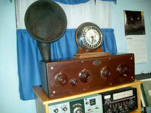
Figure 9.6 Restored Atwater-Kent Model 20.

Figure 9.7 Chassis of Atwater-Kent Model 20.
In figure 9.7 from right to left the tubes' functions are; first RF amplifier, second RF amplifier, grid leak detector, first audio amplifier, and audio output amplifier. The round can which appears to be behind the detector tube is an audio coupling transformer between the detector and first audio stage. There was another one which was between the first and second audio stages which had an open primary. When this picture was taken the second audio interstage transformer had been replaced by a modern one. It can't be seen in the picture. I melted the tar in the defective transformer and pulled the guts out of the can. I installed the now empty can over the new transformer to give the radio an authentic look. In case you have a similar problem the new transformer came from Antique Radios inc. The original transformer is wound with many turns of very fine wire and is lacking in the complete magnetic circuit we know from modern transformer designs.Troubleshooting.
Figure 9.8 Schematic of Atwater-Kent Model 20.
This radio is so simple there isn't really much to go wrong. The one I restored probably presents a typical set of problems. There was no plate voltage on the first audio stage because the interstage transformer was open. When I connected a 100 k ohm resistor from B+ to the plate the radio began to work, sort-of. I found the grid leak resistor which is specified as having the range of 2 to 4 meg ohms read approximately 15 megs. I soldered a 3.3 meg ohm resistor under the chassis where it is out of sight. I left the snap-in grid leak in place for appearance.Why did the radio work with an open audio transformer? Evidently there was enough capacitance from the primary to the secondary and enough secondary inductance to couple signal from the plate of the first audio to the grid of the audio output. After installing the replacement transformer the audio quality was not improved very much. As you can see from the first picture above I am using the radio with the wrong speaker. This is in fact an RCA horn speaker. The Atwater-Kent speaker may have better quality. I am on the lookout for one.
The operating instructions I found on line state that the B+ should be 90 volts. In fact the radio performs much better at 40 volts. This must have extended the useful life of the B battery. The instructions are also written for use with a 6 volt storage battery as the A source. I used a 5 volt logic power supply which matches the 5 volt filaments in the tubes. This means I don't have to be as cautious with the filament rheostats as the instructions state. These rheostats are the only means of volume control.
To say the radio is difficult to tune is an understatement of gigantic proportions. With patient tuning I have managed to find some distant high power stations at night. It actually helps to have a noisy fluorescent lamp on the table next to the radio. Turn it on to peak the tuned circuits and off to see what's on that frequency.
The model 20 dates from about 1920. TRF radios were improved through the 20 as manufacturers figured out how to make the circuits track. At first the three knobs were reduced to two with each one controlling two tuned circuits giving a total of three amplifier stages and finally with higher gain tubes one knob controlling three tuned circuits while returning to two amplifier tubes.
Although the super heterodyne circuit was invented in 1916 I'm not sure when it came into the radio market but I am sure it was phased in gradually. It seems to have been well established by 1930.
Back to Fun with Transistors.
Back to Fun with Tubes.
Back to Table of Contents.
Back to top.
9.3 Pre World War Two Radios.
By 1930 the superhet was well established so any radio of this vintage you encounter is more than likely to be of this design. Now we will study the principles behind the superhet.The Super Heterodyne Radio.
It's hard to say why the heterodyne radio was considered super. I suspect it was marketing ad verbiage. In any case we are stuck with the term and most of the time it is shortened to superhet.The TRF radio receivers have brought us up to about 1925. The principle of heterodyning had been developed by Edwin Armstrong in the 19 teens and patented by him in 1916. An early version was offered to the public as early as 1919 but it really didn't catch on in the consumer market until the late 1920s.
The Principle of Heterodyning
Heterodyning is more commonly known as "mixing", "conversion" or "modulation". OK; but what is it? If you combine two frequencies in a device known as a "mixer", "converter" or "modulator" you get two new frequencies. These new frequencies are the sum and difference of the two original frequencies. For example if you combine 5 MHz and 6 MHz in a mixer you get the two original frequencies and in addition you get 1 MHz and 11 MHz. If you combine 650 kHz and 1105 kHz you get 455 kHz, 650 kHz, 1105 kHz and 1755 kHz. There are some types of mixers in which the original signals are canceled out and ONLY the sum and difference frequencies appear in the output. These devices are called "doubly balanced mixers" or DBMs for short. We will likely get to them in time. But for now we will be talking about mixers in which the original two signals appear in the output along with the sum and difference frequencies.So What is a Mixer?
Well, it's any nonlinear device. A nonlinear device is anything that has a graph that isn't a straight line. A diode, either vacuum or semiconductor makes an excellent mixer. A tube or transistor which is being driven into overload is another excellent mixer. The balanced variety consists of combinations of diodes and transformers, or transistors (usually in an integrated circuit). There was even a special tube developed in the 1960s that was a balanced mixer.The Superhet Receiver.
In connection with the TRF receiver I mentioned that tracking of the tuned circuits was a problem. But the major problem with TRF receivers is changing selectivity as you tune across the band. The stations at the high end (near 1600 kHz) tune more broadly than the stations at the low end (near 540 kHz). If there are two stations close together in frequency at the high end you would have trouble separating them. This is not a problem at the low end.The reason for this is that selectivity (or bandwidth) is a constant percentage of the center frequency. Suppose the Q of a tuned circuit is 40. At a frequency of 600 kHz the bandwidth is 15 kHz. That's about right for AM reception. On the other hand the bandwidth at 1500 kHz is 37.5 kHz. There is no way around this. We would have to repeal some of the laws of electricity and magnetism to keep this bandwidth change from happening.
If we could find a way to change the frequency of any given station to some predetermined frequency we could build a set of tuned circuits and amplifier stages that would always have the proper bandwidth and we wouldn't have to worry about tracking because the frequency of the circuits will never be changed. Calling up the station and asking them to change frequency doesn't seem to be a practical solution. We need some way to change the frequency after the station's signal enters our radio.
Are you ahead of me? Yes. The mixer is it. The frequency we generate to combine with the incoming station is produced within our own circuitry so it is local. It is called the "local oscillator". Let's say we have constructed a fixed tuned amplifier at a frequency of 455 kHz. (That's the almost universally used frequency for this amplifier. Car radios usually use 262 kHz. I don't know why.) So if we want to listen to a station on 780 kHz we must tune our local oscillator to 780 kHz + 455 kHz = 1235 kHz. The 1235 kHz local oscillator combines with the incoming station at 780 to produce two new frequencies at 455 kHz and 2015 kHz. The tuned circuits select the frequency at 455 kHz and reject all others. The frequency of 455 kHz is in-between the station's frequency and the audio frequencies so it is called the "Intermediate Frequency" or just IF for short.
Image Frequencies
Suppose you live in Cincinnati so you have a strong local station on 1530 kHz. (It used to be WCKY; I don't know if it has changed. I haven't heard it in a long time because it skips over me here in BG KY.) Well, suppose you would like to listen to an out of town station which is operating on 620 kHz. You tune your local oscillator to 620 + 455 = 1075 kHz. What do you hear? Well, WCKY on 1530 is also there and combines with your local oscillator on 1075 to produce a difference frequency of 1530 - 1075 = 455 kHz. OOPS! That's the main drawback to a Superhet receiver. It receives two frequencies simultaneously at the same time. It's up to the antenna coil which is tuned to 620 kHz to reject the strong signal on 1530 so you can listen to the station you want to hear. A really good AM radio will have an amplifier stage before the mixer, called the "RF Amplifier" or "RF Stage" with two tuned circuits to make sure you are only listening to one station at a time.The 1930s are often referred to as the golden age of radio. Most of the people who use this phrase are thinking of radio programming content. However it was also technically the golden age of radio. The difference between a 1930 model and a 1940 model is striking. Probably the most striking improvement to a nontechnical person would be sound quality. But there were also large improvements in reliability, stability, and ease of tuning.
Many consoles incorporated record players and a few even had the newest thing, FM radio. Many had push-pull output stages some boasting output power of 25 watts.
At the other extreme there were still many battery radios which were not intended as portables. These days they are called farm radios because they were intended to be used on farms where there was no electricity at all or if there was electricity it was 6 or 32 volts DC from a gasoline powered generator and a system of storage batteries.
Types of farm radios are as follows.
- Dry battery only. The source of power was a large cardboard box containing A and B batteries that sat in a compartment in the bottom of the radio. When the batteries ran down the user had to buy a new one. I suspect that when the battery pack went dead that many farms did without radio during the depression.
- Dry B battery and storage battery for A battery. If a means existed to charge batteries this was a good solution. A single B battery was less expensive than an A-B pack. In some radios the A battery was a 2 volt single cell lead acid battery. In others it was a 6 volt battery of the same type.
- Vibrator derived B+ from a 6 volt storage battery. Many farms had wind powered 6 volt generators that kept one or more 6 volt lead acid batteries charged. A 6 volt radio could operate well from such a system without the ongoing expense of buying replacement B batteries.
- 32 volt vibrator radios. Other farms, such as the one I grew up on, had a Delco gas powered 32 volt DC generator system. A bank of five 6 volt batteries were charged daily by the generator. The trick was to manage the power usage so there would be enough juice left in the batteries the next morning to start the generator. In addition to making electricity the generator made enough RFI to make radio listening impossible for all but the strongest station which was WHO in Des Moines.
Troubleshooting.
What all these radios have in common are tubes, resistors, capacitors, and inductors. The same kinds of component failures afflict all 4 types. Remember to half split at the volume control and then signal trace or signal inject to find the defective stage.One component found in two of the types is the vibrator. Because it is an electro-mechanical device it is the least reliable part in the radio. If you are asked to repair one of these sets you may find that the vibrator can't be made to function. There are companies you can find with a Google search that will provide vibrator replacements that use transistors as the switching elements. You really don't have any choice in replacing this part. Nobody is making mechanical vibrators anymore. In addition the owner will likely want you to build a suitable DC power supply to run the radio. This should not be difficult in this age of power transistors and IC voltage regulators. Remember that the original battery gave a wide range of voltages from fully charged to near run down. Any power supply does not have to be regulated within 1 millivolt or even 1 percent.
AC Powered Radios.
Refer to "Steps to First Power on" Above. Near the end of the decade early versions of the All American Five were beginning to be seen but most of the line powered radios you will encounter will have power transformers. This is both a blessing and a curse. The blessing part is that the circuitry is isolated from the power line making the set safe to work on. The curse is that the transformer may be burned out and you will have to find a replacement for it. Hammond makes a wide range of power transformers so you won't have any trouble finding a good electrical match for the original but physical mounting will be the major problem. If you are lucky the replacement will mount in the same way and it will fit in the allotted space. You may have to drill 3 new holes in the chassis to mount the new transformer. If you are unlucky there a whole host of problems that can rear their ugly heads to make your life difficult. You won't know for sure what you need to do until you have the replacement transformer in hand.Some Common Problems.
At this point it is assumed that you have troubleshot the power supply section and replaced all capacitors except micas. One common problem you may have already found is for the field coil of the speaker to be open. Now the issue of authenticity versus cost of repair comes into play. In most radios the speaker field coil was used as a filter choke in the power supply. There are companies out there that will rebuild old speakers including field coil and cone and voice coil replacement. I'm not going to quote a dollar figure but it is likely to cost you more than two limbs. The easiest solution is to buy a modern permanent magnet speaker of the correct size and install it. The diagram is likely to state the resistance of the field coil and a resistor close to this value should be installed in its place.If after the radio is working you hear hum in the speaker you may need to add a filter choke in series with the resistor. 5 henrys will usually be enough. The filter choke may not be required if the filter capacitors which were quite small in the original were replaced with larger values. For example it was not uncommon to find filter capacitors of 2 or 4 microfarads particularly in radios of the early 30s. If you replace these with 22 or 47 uf caps the resistor will usually provide sufficient filtering. Leave the can capacitors standing on top of the chassis and install the modern ones under the chassis out of sight. Don't forget to disconnect the old capacitors.
The oscillator and antenna coils in these radios may be quite fragile and a touch or unfortunate bump from a tool may cause it to disintegrate. If this happens don't despair. Antique Electronic Supply has an assortment of oscillator coils and a few antenna and RF coils. The ones made by Hammond are the best.
The if transformers are a different story. The fragile coils are encased in square cans and are not likely to suffer any accidental physical damage. If one is found to be open you may be out of luck. Your best chance is to substitute an IF transformer from a 1950s or 1960s radio. The only alternatives are winding a new one or make one out of RF chokes. Either way it's going to be a lot of work.
In some 1930s Philco radios I have seen there are capacitors that are disguised as terminal strips. They have 3 terminals mounted on a black Bakelite block. Inside the block is a capacitor and it has a 99% chance of being too leaky to allow the radio to work properly. These will be found in the audio section used as coupling capacitors. Some people melt the tar out of the block and install a modern capacitor in it. I simply mounted a modern terminal strip on the mounting screw and connected a new capacitor to it. I jumpered from the input side of the capacitor to one side of the new capacitor and unsoldered the wire to the grid and the grid resistor from the block and soldered it to the other side of the new capacitor. The capacitor blocks were left in place so as not to preclude a more authentic restoration in the future.
One more thing you are likely to encounter is a noisy volume control. Most pots have a small slit opening behind the terminals. Turn the radio so the terminals are up and use a medicine dropper to drop control cleaner at the slit. Rotate the control vigorously to work the cleaner into all of the rotating contacts. If the radio has short wave bands the band switch will also need cleaning. I have seen many radios in which the switch was so dirty that the radio would not work. If the audio section is functioning but the radio is silent clean the band switch first.
Back to Fun with Transistors.
Back to Fun with Tubes.
Back to Table of Contents.
Back to top.
9.4 The All American Five.
During World War II the American electronics industry turned its efforts to supplying military electronics and there were very few if any civilian radios built in the years 1942 through the first half of 1945. At the end of the war the industry started cranking out a simple and inexpensive, some might even say cheap, table radio that became known as the All American Five.This radio circuit represents a triumph of the bottom line over quality and safety. It was the radio that the Atwater-Kent company went out of business rather then make. Every feature had one purpose, to reduce the cost of manufacture. After World War II there were millions sold under hundreds of brand names from Admiral to Zenith.
Much scorn has been heaped on the little AA5 by myself and others but the truth is it's a wonder of design and simplicity. The word is starting to get around and local antique dealers are bringing me their AA5s to put into operating condition. I have had the opportunity to see a great many different radios. The marvel is how well they work considering their construction. There's no such thing as a wiring harness. Wires go every which way, crossing over, twisted around, power next to audio, audio next to RF, power next to RF. Terminal strips are seldom used or used in great moderation. That sometimes means that wires are just brought together in the middle of the air and soldered together. Yet still they keep on ticken'. The design has been so well refined that it seems impossible to build one that won't work.
It is called the All American Five because all brands were made in America. This was long before the mass exodus of the electronics industry. The five comes from the fact that it used 5 tubes. There were variations using 4 tubes which didn't perform very well and 6 tubes which cost more. The average person who didn't stay up late to see how many distant stations they could hear (known as D X ing) didn't care about the improvements provided by 6 tubes. Consequently the All American Five became a post war standard which did not fade away until replaced by the All Japanese Six, the six transistor radio made in Japan.
The most prominent feature of the AA5 was that it had no power transformer. The result was that the circuit common was connected to one side of the power line. Because there was no polarized plug there was a 50 - 50 chance that the radio's chassis would be connected to the hot side of the power line. Very late models from the sixties were carefully designed not to have any metal parts on the outside even going so far as to recess screws in deep holes. In the 40s and 50s there was no such concern on the part of manufacturers. It was common to see chassis mounting screws exposed on the bottom of the plastic case. These radios could be, and sometimes were, lethal. All it would take was for an unwary person to complete the circuit between a metal part on the radio to a kitchen sink. I once owned one that was in a metal case. My friends and I called these radios "suicide boxes".
Most people who owned and used them were blithely unaware of the danger. I'm sure it must have cost some of them their lives. One side of the power line connects to the chassis. Depending on how it happens to be plugged in the chassis could be "hot" 120 volts above power line ground. Most of them have the switch in the chassis side of the line which means that even if you have it plugged in correctly, when you turn the switch off the chassis will be electrically hot. With these units there is no right way to plug them in.
A Change For Safety.
First of all you should have replaced all paper capacitors with modern or with X or Y rated capacitors as described in section 9.1 above. Following that there is another change which must be made to make an AA5 safe to work on and use. Here is how most AA5s have the power switch wired.

For a verbal description click here.
The common wiring method had one side of the line cord going to a pin on the rectifier tube and the other side going to one terminal of the on/off switch. The other terminal of the on/off switch went to chassis.It should be noted that not all radios used the metal chassis as the circuit common. In some radios all connections that went to common connected together with wire usually at a terminal lug. From this point there was a resistor and capacitor in parallel to the chassis. Commonly used values for these were 220 k ohms and 0.001 uf. When modifying such a radio the 0.001 uf capacitor should be replaced with one that is X rated. When the instructions below refer to the chassis the common point is meant.Suppose you plugged it in so the chassis was "cold" when the radio was turned on. That would mean that the bottom prong of the plug was connected to the power line neutral. Everything would be fine until you turned the radio off. Now the top prong of the plug is connected to the hot side of the power line. The tube heaters are cold and have a very low resistance (very approximately 100 ohms). This resistance is connected from the hot side of the power line to the chassis of the radio. You could connect a clip lead from the radio chassis to a water pipe and the radio would come on and play. If part of your body should complete the circuit instead of a clip lead you might never play again.I strongly urge modification of the radio circuit to make it somewhat safer. Here's the diagram.
For a verbal description click here.
Before starting to modify the radio go to a discount store and buy a polarized 2 prong plug extension cord. They are usually a dollar or less. Cut away the old power cord but leave short pieces of it on the rectifier tube and switch. If the insulation is in good shape (not always the case in these old sets) leave enough wire to reach to the switch. If the insulation on the old cord is rotten replace it with a piece of wire cut from the extension cord. Decide how long you want the new cord on the radio to be and cut the cord that length from the plug end. You will most likely never find a use for the socket end so cut off the extra cord, save it, and throw the socket end away. Thread the new cord in through the chassis hole, and secure it in the same manner that the old one was, for example tying a knot in it.Separate the two wires for a couple of inches, and strip about 1/4 inch of insulation off the ends of the wires. Twist the fine strands of wire tightly together and melt a small amount of solder over them to hold the strands together. This is known as tinning the wire.
Now remove the wire connected from one side of the switch to the chassis. Strip and tin the piece of wire connected to the rectifier tube socket. Connect this wire to the terminal of the switch you just removed the chassis grounding wire from. Solder the wire in place.
Remove the piece of old line cord from the other terminal of the switch. Solder the wire coming from the NARROW prong of the new line cord to that terminal of the switch.
Solder the wire from the WIDE prong of the new line cord to the chassis connection where the switch used to be grounded.
You may find after making this modification that the hum level has increased. The phrase "lead dress" was probably never spoken in an AA5 factory so the wires go every which way. The reason for putting the switch in the neutral lead was to minimize hum transfer from the off on switch to the volume control pot. Now that the switch is in the "hot" side of the line there may be more hum than desirable in the speaker. When installing the polarized cord make sure the hot leads run along the chassis and as far away as possible from the three terminals on the side of the control. It may be best to route the wires straight down to the chassis perpendicular to the shaft. Route the leads that carry audio along the chassis and away from the power line leads. You may have to solder new pieces of hookup wire in these leads to make this possible. Experience has shown that careful routing of the leads will reduce the hum to acceptable levels.
The switch modification will make the radio much safer to use and work on but the safest way to work on these sets is to obtain and use an isolation transformer. The minimum you need is a 30 watt transformer. A higher wattage unit would give you more flexibility. It may cost you some money but how much is your life worth. If you think you are immortal or just want to live dangerously there isn't much I can say to you. If you decide to work without an isolation transformer get one of those test lights or a small night light and permanently connect one side of it to the power ground and terminate the other in a test wire. Touch the wire to the radio chassis. If the light lights up reverse the plug. Test it with the switch off. If there is no right way, plug the radio into a plug strip with a switch and use that to turn the radio on and off. Temporarily solder a jumper across the radio's off on switch to prevent yourself from absent mindedly turning it off.
Jim sent me an email in which he makes the following recommendations.
"These are excellent suggestions. However, I would suggest taking these steps further, by equipping the radio with a ground fault interrupter (GFI) .In my research, I find that many hair dryers are equipped with cords that have plugs containing the GFCI protective device. These look like wall warts on the end of the cord. I found used hair dryers in second hand stores selling for under $5 each. So, the plan is to purchase a used hair dryer with a good cord and GFCI plug, remove the cord and use it to power an AA5 radio, in one of two ways:
The simplest way to power the radio is to make the hair dryer cord into a GFCI extension cord. Purchase, from a hardware store, an outlet that installs on the end of a cord. Then, properly wire and attach the outlet to the hair dryer cord and you have a GFCI extension cord. Plug the radio into your GFCI extension cord and plug the GFCI extension cord into AC power. Secure the radio cord into the extension cord outlet, since you want the extension cord permanently connected.
The other way is to use the hair dryer cord to replace the cord that came with the radio. If you choose this method, note that the hair dryer cord is thicker than most AA5 radio cords. The entry hole into the chassis may need enlargement and the strain relief may require replacement to fit the larger cord.
Look for hair dryers with plugs that have two buttons labeled TEST and RESET. If an outlet is available in the second hand store, test for proper operation of the GFCI before buying the hair dryer.
Hair dryers have been manufactured with GFCI plugs for over 10 years now, but not all models have GFCI plugs. Therefore, check very carefully to be sure you purchase a hair dryer with a GFCI plug. GFCI plugs may also be found on hair curlers and other bathroom and kitchen electrics, so check those as well if you can't find a suitable hair dryer.
Jim also sent along this anecdote.
In my own case I repaired an AA5 radio which used a capacitor between the metal chassis and one side of the line cord. I found about 120 volts DC between the radio internal ground and chassis. I traced the problem to continuity between the audio output transformer's primary winding and its frame. The radio played well despite this problem. I remounted the transformer with insulated fasteners and spacers. GFI would have protected humans from electrical shock if I hadn't fixed the problem, or if the problem developed later.
Jim"
Testing tubes.
You don't necessarily need a tube tester. All you need is a functioning radio that has the same tube lineup as the one you're working on. In the process of testing tubes whether it's with a tube tester or another radio, NEVER PUT A HOT TUBE INTO A COLD AA5 RADIO OR A COLD TUBE INTO A HOT AA5 RADIO. What the heck do I mean by that? Here is the hot tube into a cold radio scenario. The radio you are working on lights up but doesn't work. You turn it off and take out one of the tubes to test it. You find the tube to be good, yank it out of the tester or other radio, plug it into the radio being repaired and turn it on. The heater of the tube you just switched is hot but the heaters of all the other tubes in the radio are cold. The resistance of the cold heaters is quite low while the resistance of the hot heater is close to its operating value. In the series heater circuit the highest resistance gets most of the voltage. For a few seconds the hot heater will get almost all of the line voltage. It may burn out before the other heaters warm up and start taking their fair share.The cold tube into a hot radio goes like this. You have a complete set of AA5 tubes you know to be good and decide to substitute them in to a defective radio one at a time. You turn off the radio, remove one tube, replace it with one of the same type number and turn the radio back on. The cold heater won't take its share of the voltage for a few seconds. The other tubes will proportionally divide up the over voltage until the cold one warms up. If the one you plugged in cold is one of the 12 volt tubes the chances of doing serious damage are small but still exist. If the cold one is the 35 or 50, the other tubes are going to get quite a large over voltage shot and at least one of them may not survive.
The Dial Light.
As you learned the dial light carries the B+ current. When you first turn the radio on the light glows at normal brightness for a fraction of a second and then dims down. As the tubes warm up and the radio begins to play the light comes back to normal brightness. If you turn the radio off and right back on the light will light up very bright for a fraction of a second and then dim back to normal. You don't have to do this many times before the light burns out. SO DON'T DO IT.If the light burns out the voltage across that part of the heater of the rectifier tube will go up to about 12 volts. That portion of the heater will over heat and will burn out within a few hours of operation. Since dial light bulbs are much cheaper than rectifier tubes, don't operate a radio with a burned out dial light. If you have a large collection of AA5s you should keep some spares on hand.
Troubleshooting Hints.
The most common defect of these radios is a bad filter capacitor. This is the one I have designated in the diagrams as a dual 40 microfarad at 150 volts. In real radios it could be as low as a dual 20 microfarad. The symptom is a loud hum that may be changed slightly, if at all, by the volume control. Sometimes you can tune in a station and hear it through the hum. The only thing for this is to replace the capacitor. One with this failure mode can't be reformed. You can go up in capacitance or voltage but not down. For example if the radio has a 20 - 20 microfarad at 150 volts you could replace it with a 20 - 30 at 150 volts or 40 - 40 at 250 volts.If you have a radio which lights up but has no sound try this. Touch the tip of a screwdriver to the center terminal on the volume control while touching the metal part of the screwdriver with one finger. There are two terminals on the back of the control, these are the on-off switch. You don't want to touch them! The terminals of the potentiometer are in a group of 3 and are on the side of the control. Turn the volume to middle or higher. Touch the screwdriver to the terminal and touch the metal shaft of the screwdriver with a finger. You may or may not hear a loud hum or buzz. If you do the audio section is working and the trouble is in the converter, IF or detector. If you don't hear anything the trouble is in one of the two audio tubes. Not necessarily the tubes themselves. As you learned earlier this is a form of half splitting.
Use a DC voltmeter to measure the voltages on plates and screen grids. A leaky capacitor can put a positive voltage on the control grid of the 50L6/50C5, but you already replaced that one didn't you?
If the audio section is working, try scratching on the grid terminal of the IF tube with the screwdriver. If you hear static the IF amplifier is OK and the trouble is most likely in the converter.
Check to see if the oscillator is running. The oscillator grid of the converter tube should have a negative voltage on it. A VOM won't work here. Use one of those cheap DMMs. Wind one lead of a 1 meg ohm resistor around the measurement probe. Touch the other lead to the oscillator grid terminal and read the voltage. The purpose of the resistor is to keep the input capacitance of the DMM from stopping the oscillator. You should read anything from about -2 volts to -50 volts. The reading will be about 10 % low but you're not going after precision, you just want to know if there is a negative voltage indicating that the oscillator is running.
If you are using an authentic VTVM you don't need to use the resistor. The DC probe on most VTVMs has a 1 meg ohm resistor built in and the meter calibration takes this into account.
Some AA5s might fool you because of a peculiar money saving modification. Look ahead to figure 9.11. Note the connections to grid 1 of the 1R5. You will note that there is no capacitor in the grid line and a coil that someone forgot to connect. There is virtually no inductive coupling between the tuned winding of the oscillator coil and the grid winding. The coupling is capacitive and replaces the typical 220 pf capacitor which is usually found here. I have worked on such an AA5 and I can say that it does work. It strikes me as going to great lengths to save a few cents on one capacitor per unit. It must have been economically feasible or it wouldn't have been done.
One more thing you are likely to encounter is a noisy volume control. Most pots have a small slit opening behind the terminals. Turn the radio so the terminals are up and use a medicine dropper to drop control cleaner at the slit. Rotate the control vigorously to work the cleaner into all of the rotating contacts.
Variations on a Familiar Theme.
As I noted earlier there was an All American 4 which didn't work very well and an All American 6 which worked very well but cost more.In some radios, particularly AM/FM there wasn't enough heater voltage for the rectifier so the 35Z5/35W4 would be replaced by a selenium rectifier. If you get one of these go ahead and replace it with a silicon. The extra voltage won't hurt anything in this case.
In the AA4, 35 + 50, + 2 X 12 doesn't add up to the line voltage. A tube manual I have from 1946 lists 45Z3 and 45Z5 which could have been substituted for the 35Z5 in an AA4. I once owned one of these radios and it didn't use one of these 45 volt tubes. I assume that most other AA4s used a fixed resistor to drop the extra voltage as mine did.
AA6s on the other hand needed a lower voltage tube in one of the sockets. The 35L6 and 35C5 were made for this purpose. I have seen AA6s which had a 50L6 in the output tube socket while the schematic listed a 35L6. Either someone didn't know or didn't have a 35L6 in stock and decided to send the radio home with a 50L6 to get the radio working rather than wait to order the correct tube.
Millions of AA5s were made and thousands have been restored. There are still tens of thousands out there waiting to be restored. Have fun.
Back to Fun with Transistors.
Back to Fun with Tubes.
Back to Table of Contents.
Back to top.
9.5 Three Way Portable Radios.
The 3 way portable radio was call that because it could operate from AC line, DC line, or an internal battery pack. They ranged in size from small enough to fit into a large coat pocket to luggables that were about 12 inches wide and 10 high. I owned one of the latter which wasn't very heavy without the battery but when batteried up was quite a load. It was a Motorola model 6L1. I don't have it anymore but I spotted it on a museum site and found the schematic on Nostalgia Air. I suppose it was for sentimental reasons that I have chosen this circuit to represent 3 way portables.

Figure 9.11 Schematic of 3 Way Portable.
Upon examining this schematic the first thing that struck me was that AGC is applied only to the RF tube and no other. After a few minutes of puzzlement I got it. The 1U4 is a sharp cutoff pentode. A remote cutoff pentode can provide gain control over a wide range even for voltages measured in volts or even 10s of volts. if this is attempted with a sharp cutoff tube serious distortion of an amplitude modulated signal will result. A sharp cutoff can be used as a gain control element if the signal level is kept small, in the single digit millivolts or below. That is exactly what is being done in the RF stage of this radio.I remember that the AGC action was about the same as an AA5 but not as good as an AA6 wherein the AGC is applied to RF, converter, and IF stages. In keeping with small voltages approximately 25% of the derived AGC voltage is applied to the control grid of the RF stage. I assume that the tapped secondary of the RF plate coil and the resistor in series with grid 3 of the 1R5 is to improve performance under extremely strong signal conditions. I don't remember it ever being blocked even when riding in a car with it and driving past a radio station's tower.
The oscillator needs a special note as this method of coupling to grid 1 of the converter tube is used in many AA5s as well. What appears to be a link winding which has one end not connected is just that although there is probably very little in the way of magnetic coupling going on. Capacitance from the tuned section of the oscillator coil to the link replaces the mica capacitor which is usually found here. This strikes me as going to great lengths to eliminate one capacitor but the economics must have worked or it wouldn't have been done this way.
Note that local audio ground is established from the negative side, pin 1, of the filament of the 1U5. You may find the filament string a bit tough to tease out so here is a simplified diagram of the chain.
Figure 9.12 Filament circuit of 3 Way Portable.
The two resistors associated with the 3V4 are to conduct the plate and screen current to ground. Without them this current would flow through the filaments of the other tubes. You will note that the filaments are a little starved for voltage and they are not all equal. When the applied voltage is 9 volts as when operated from batteries the voltages will be a bit higher. There should be more resistors for cathode current along the line. The Zenith Transoceanic has several resistors to ground along the filament chain. I don't see that adding these resistors would significantly affect the battery life. I'm sure they were left out to reduce the manufacturing cost.The two 1 k ohm resistors shown in this diagram are actually the 2 k ohm tapped resistor shown in the complete diagram above. This resistor became open while I owned the radio and before I had acquired sufficient skill to replace it myself. I suppose that just one of the sections opened up. The service shop where I took it made no attempt to obtain the original Motorola part. Instead they hung a 10 watt resistor by stiff wires coming through a hole drilled in the chassis. If I still had the radio I would do something about this.
Troubleshooting.
I have already pointed out the most likely failure in the radio. The 2 k ohm resistor is dissipating 5 watts and is the most likely component to fail.Remember that the selenium rectifier should be replaced with a silicon diode. Do not give in to temptation to leave it in place. When a selenium rectifier fails it gets hot and some of the selenium is oxidized. Selenium is in the same column of the periodic table as sulfur and shares some of its characteristics. Of interest here is its oxide. Sulfur dioxide and selenium dioxide are both rather poisonous. Also they both smell like rotten eggs. If you are working on a radio that still has a selenium rectifier in place and you smell rotten eggs, unplug the radio and open the windows. A selenium rectifier is a poison bomb waiting to go off. Physically remove the rectifier from the radio because some future owner might try to restore it to authenticity by reconnecting it. Use a shorter machine screw than was used to mount the rectifier and mount a terminal strip. Connect the wires that originally went to the rectifier and solder a silicon diode in place of the rectifier. The plus marked side of the selenium corresponds to the banded, cathode, end of the diode.
The value of the 150 ohm resistor will most likely have to be increased to keep the voltage at pin 7 of the 3V4 from exceeding 9 volts. Actually 9 or even 9.5 volts at this point wouldn't hurt any. If you are uneasy with the differing voltages along the filament string you can always do a little re-engineering by adding equalizing resistors.
If the 20 uf capacitor shorts it would most likely take out the top half of the 2 k resistor especially if the owner unwisely left the radio turned on even though it was silent.
If the 80 uf capacitor shorts out it will also silence the radio but it is unlikely that any additional damage will be done even to the 3V4. The 2 k resistor from the 105 volt supply is almost a constant current source and the 3V4 will not sustain any damage.
Elsewhere the circuitry is not unlike an AA6 so if the filaments have proper voltage but the radio remains silent all you need to do is round up the usual suspects.
If you or the owner wants battery capability you will have to construct a battery. If you are extremely lucky you will be able to find an AB pack that fits the radio. You might even find one still in it. It will be run down long ago but you can use the box and the connector socket. If not you will have to devise a method of connecting the battery that is easy to connect and disconnect.
The 90 volt B battery is easy. Just ten 9 volt transistor batteries will do perfectly. I have heard of people making up the B battery from AA cells but I view this as overkill. The current drawn from the B battery is less than that drawn by a 6 transistor radio so the 9 volt batteries should last a long time. In the original AB pack the A battery was made up of F cells which was probably overkill. After the B battery was run down I could get several months of experimentation out of the A battery. Modern D cells or even C cells should do the job nicely. It may be that the B battery was intended to run down so the user would stop using it before the A battery lost sufficient voltage to damage the filament's coating from being operated below design temperature.
One more thing you are likely to encounter is a noisy volume control. Most pots have a small slit opening behind the terminals. Turn the radio so the terminals are up and use a medicine dropper to drop control cleaner at the slit. Rotate the control vigorously to work the cleaner into all of the rotating contacts. If the radio has short wave bands the band switch will also need cleaning. I have seen many radios in which the switch was so dirty that the radio would not work. If the audio section is functioning but the radio is silent clean the band switch first.
Back to Fun with Transistors.
Back to Fun with Tubes.
Back to Table of Contents.
Back to top.
9.6 Phonographs and Record Changers.
As far as I can tell the first electric phonographs intended for home use appeared about 1930. At one time I actually had ownership of a variable reluctance pickup cartridge intended to adapt a spring driven acoustic phonograph to electrical reproduction. I couldn't make it work and not realizing the antique value even of a nonfunctional unit I either threw it away or gave it to a friend. Oh, the indiscretions of youth.Beginning after world war II the crystal phonograph became very popular. I owned one myself. These players used a Rochelle salt crystal cartridge which delivered about 6 volts into a 500 k ohm load. This high output meant that only one amplifier tube was required. The diagram is shown below.
Figure 9.13 Crystal Phonograph.
There were other variations than those indicated in the schematic. The first electric phonograph I owned used a 117L7/M7 which incorporated the rectifier and the power amplifier into the same envelope with a 117 volt heater. Another variation I saw used a selenium rectifier and a 25L6 amplifier. The motor had been designed to operate from 92 volts at a current of 300 mA. The motor was in series with the heater.If you find one of these phonographs your chances of ever getting it to operate in its original state are absolutely zero. The reason is the crystal pickup. Rochelle salt is a very hydroscopic material. That means it loves water and will grab onto any stray water molecules that come by. My original phonograph was bought and used for about 2 years in Iowa. Then we moved to Florida. In that humid climate it only lasted about 6 months. After having the cartridge replaced for a cost of 8 dollars it went out after another 6 months. 8 dollars was a considerable sum of money in 1952 and my mother said I would just have to do without rather than spend another 8 bucks on another crystal. The symptom is the sound grows progressively weaker and weaker until the volume control is up all the way and from that point it fades out to inaudibility. No doubt one of these cartridges would last for several years in Arizona but humid climates are death to them.
If you must get one of these phonographs restored to operation the only way I can see to do it is to install a ceramic or even a magnetic cartridge and install a transistor preamp to bring up the level to that required. It could easily be powered from the DC level at the cathode of the power tube and hidden in an electrolytic capacitor can.
A much better phonograph was the one with two stages of amplification. If you take away the 12SA7/12BE6 and the 12SK7/12BA6 from an AA5 and replace the heaters of the missing tubes with a 150 ohm 5 watt resistor you have the circuit of a ceramic phonograph. These were a little more expensive but if you lived in a humid climate the difference would be made up in a year. The reason that more gain was needed was that the ceramic cartridge output was less than 1 volt.
Other than the cartridge the filter capacitor was the part most likely to fail. In an old player this is one of the parts that should be replaced as a matter of routine.
The test for either a one stage or two stage phonograph amplifier is to lift up the arm with the unit turned on and the volume up all the way. Touch the cartridge pins one at a time while not touching anything else. If you hear a loud hum when touching one the amplifier is alright and the cartridge is dead. Even ceramic cartridges can go dead after 50 years. Although I do have a Silvertone wire recorder and phonograph that has a working ceramic cartridge in it. The sound is a little weak but it is still usable enough to record from a record to wire.
Record Changers.
I don't know when the record changer was invented but I once owned one that dated from about 1940. It made an incredible amount of mechanical noise. The change cycle began with a metallic bang that was a projection on the rim of the turntable hitting a lever which the eject button or the arm tracking the eccentric groove at the end of the record had pushed into the path of the projection. This raised a roller that engaged a spiral groove in the bottom of the turntable. This pulled the roller toward the center of the turntable which moved the rack in one direction. When the roller reached the end of the groove an inclined plain pushed it down which caused another one to pop up that was positioned at the beginning of the groove. This was the halfway point of the cycle. The second roller was pulled toward the center which moved the rack back in the other direction. The incline pushed the roller down completing the cycle. The rollers in the groove were metal on metal. The cycle sounded like this. Music ends, record scratch, click bang, grind grind grind, flop as the record dropped, grind grind grind record scratch, music starts.The odds of either one of us encountering this exact model are small although I must say the movement was quite robust and as long as I kept things oiled it worked fine.
The three types you are most likely to encounter are the ones made by BIC, yes, that's the same as the pen company, VM (Voice of Music), and the RCA 45. The BIC name is not on every changer built by BIC. They made drop in changers for console units made by many different manufacturers. Most manufacturers put their own name on the changer. VM also made changers for consoles but you are apt to see the VM name plate on these changers. I suspect that VM wrote a clause in their contracts that required that the VM name remain on the changer.
The BIC and VM changers worked much the same. There are gear teeth cut into the bottom end of the turntable bushing. The change drive is a gear about 5 inches in diameter with a gap at one point. During play the gap is positioned around the gear on the turntable. When the cycle is triggered a small projection is moved forward which catches the teeth and turns the change drive gear just enough to engage its teeth in the turntable's gear. There are various grooves and projections on the change gear that move the arm, activate record size detectors and initiate record drop. The change cycle takes place over about 4 revolutions of the turntable.
The RCA 45 was another of those innovations that comes along about once in a generation. It and the records it played had been designed for each other. The entire change cycle took place in a single revolution of the turntable.
Troubleshooting.
If the turntable runs the most likely problem is that it stalls when going through the change cycle. One cause of this is a slippery idler wheel. If you do a Google search you may be able to find a replacement idler wheel or the rubber tire that goes around it. One thing you may be able to do is to remove the rubber tire, turn it inside out, and reinstall it. This exposes rubber which has been protected from the ravages of time. Be warned, the tire may be too fragile to withstand this treatment. If the previous option is out of the question but the tire has not totally disintegrated you may be able to resurrect it by roughing the surface with sandpaper or a file. Be careful not to create flat spots. A change in diameter of the idler will not alter the speed of the turntable. Sometimes it is necessary to shorten up the idler spring a little but don't carry this too far.Another cause of stalling is a frozen up bearing in the changer mechanism. The lighter hydrocarbons in the oil have evaporated leaving behind a substance that is more like tar than anything else. The bearings most likely turn with great difficulty if at all. The right way to treat this condition is to completely disassemble the mechanism and soak all parts in a degreaser, then relubricate with sewing machine oil and reassemble. I must admit that I have never felt up to such a time consuming procedure with its high risk of losing parts or forgetting how they go back together.
One way is to simply flood the bearings with new oil and wipe up the excess. The idea is to flush out the heavy hydrocarbons and replace what's in the bearings with good oil. In particularly stubborn cases WD-40 can be used to flush out the tar and then oil the moving parts. DO NOT LEAVE WD-40 IN THE BEARINGS. It is NOT a lubricant. You MUST replace the WD-40 residue with real oil or they will freeze up tighter than they were before.
You should use a very light oil on the parts of a record changer. The old hardware store standby 3 in 1 will do but it will tar up again in a few years. Sewing machine oil is a much better choice and you don't have to look very hard to find it.
Troubleshooting a record changer can be difficult because it is hard to see what's going on under there. Here is a way to get the inner workings into the open and still allow it to be operated.
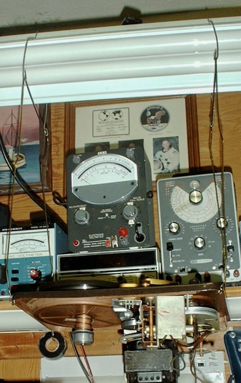
Figure 9.14 Hang the Changer by Wires.
This picture shows the transport mechanism from a Silvertone wire recorder hung by coat hanger wire from my workbench light. The florescent fixture is hung from the ceiling by chains attached to screw hooks that go into ceiling joist. Any record changer can be hung in the same way. The wires pass through hooks in wires that go over the top of the fixture. This is so the wires can be folded up against the fixture out of the way when not in use.Once the bearings are properly lubricated and running freely the changer will work most of the time. If it doesn't there may be a missing spring, misadjusted or misaligned part, or a worn part.
Ace hardware does stock a few helical springs and if you need one of those you may be able to find it. If a flat spring is called for it may be harder to find. Flat springs are found in old windup clocks. Here is a case where you may need to sacrifice one antique to restore another one.
Misalignment is sometimes the result of a missing screw. They do tend to vibrate out and get lost. Finding a new screw shouldn't be hard even if it is metric. Changer parts often pivot on nylon inserts. Do not oil these. If a previous owner did the insert has likely disintegrated and needs to be replaced. Such parts may be very hard or impossible to find. If you have some skills with files and other small hand tools you may be able to fabricate one out of aluminum or hardwood. If made of wood the friction surface should be heavily waxed, not oiled.
A previous owner may have bent a part for some reason known only to that person. Bending it back is probably the only solution but be cautious. Metal fatigue can set in very quickly particularly if the part is made of aluminum. If it breaks you are probably back to fabricating a new part.
If a part is just worn out the only option is to make a new one as indicated above.
Sometimes a changer will be just so worn out that it can't be restored. One option is to disable the change mechanism by removing the change cycle initiation part or parts and using it as a single play turntable. Another option is to say "it can't be fixed". If you are working on it for someone else and they insist that they want it to work you may have to say "take it to someone else".
Back to Fun with Transistors.
Back to Fun with Tubes.
Back to Table of Contents.
Back to top.
9.7 Consoles and High Fi Components.
High fidelity seems to have come into existence sometime after World War II. I'm going to put it at about 1950. By 1955 the word if not the sound had become rather prevalent if not ubiquitous. Many older console designs were given a facelift, labeled as high fidelity usually in script, and remarketed with few or no internal changes.These renamed consoles usually featured a 12 inch electro magnetic speaker, push-pull outputs and no negative feedback. The power tubes were most likely to be 6V6s although some had 6F6s or 6K6s. A few did have 6L6s. These were monophonic. The output transformer was usually mounted on the speaker. Although stereo was introduced in late 1957 it did not really catch on with the general public until after 1960.
Phase Inverters.
Because most of these consoles had push-pull outputs the phase inverter circuit is important to the performance of the set. The earliest consoles used a circuit known as the open loop phase inverter. An example circuit may be seen at this location. Look at the first diagram on the page. Use your back button to return here. The duo triode would likely be a 6SN7 rather than the 12AU7 shown, and the single triode would likely be a 6J5. Resistor values would be different.A variation on the open loop is the closed loop phase inverter. Negative feedback is used to make the circuit self balancing as shown below. This circuit was found in a Westinghouse console.

Figure 9.15 Closed Loop Phase Inverter.
The 220 k and 270 k ohm resistors form a voltage divider across the two output tube (6V6) grids. When the voltages at the two grids are equal in amplitude and opposite in phase the voltage at the junction of the two resistors is just what is needed to make the AC voltage at the plate of the second 6AT6 exactly what it should be. If aging tubes imbalances the drive to the two 6V6s, say to reduce the drive to the bottom tube, the voltage at the junction of the two resistors will increase driving the grid of the lower 6AT6 harder partially restoring the voltage to its proper value.The diodes in the first 6AT6 are used as the AM detector as in the all American 5.
Troubleshooting.
First of all it is assumed that all capacitors have been replaced or reformed as appropriate. All resistors should have been checked and replaced if out of tolerance.If the set still doesn't work the band switch probably needs attention. Older consoles are very likely to be either AM/FM or AM/SW or even AM/SW/FM. There may also be a phono position for a record player included in the console. Silver plating of switch contacts was common in this era as it is today. Silver can be oxidized to the point of making poor or no contact. The rubbing of contacts together which keeps them clean when in daily use is not sufficient when a radio has sat unused for several decades. Contact cleaner applied to the switch contacts will very likely restore the set to operation.
Other causes of non operation could be an open speaker field coil. Even if the set plays, check the plate voltage on the plates of both output tubes. If one side of the output transformer is open there may be no noticeable effect on the sound at low listening volume. The tube on the open side which has screen voltage but no plate voltage will not last very long under these conditions.
The record player, usually a changer, likely employs a ceramic pickup cartridge. Unless the set has been stored in a very damp basement, chances are good that the cartridge is still good. In units made in the late 40s and early 50s the changer was most likely a single speed 78 RPM player. I have seen many consoles from this era in which the original changer had been pulled and a 3 speed or 4 speed changer dropped in its place. At some time the size and mounting of record changers was standardized which made a drop-in retrofit possible.
Another thing you are likely to encounter are noisy volume and tone controls. Most pots have a small slit opening behind the terminals. Turn the chassis so the terminals are up and use a medicine dropper to drop control cleaner at the slit. Rotate the control vigorously to work the cleaner into all of the rotating contacts.
High Fi Components.
High fi components basically took the parts of a console radio phonograph and packaged each separately. Because customers were willing to pay more for quality components they were all more elaborate than would be found in a typical console.The radio section was marketed as a tuner. Invariably FM and usually including an AM section as well. The FM section was as good as the state of the art at that time permitted. Sometimes the AM section was skimped although it was often of a high quality.
The amplifier would always have negative feedback, lower distortion, and more power than a console. In the bottom of the line amplifier the output tubes would be 6V6s but higher priced amplifiers would have 6L6GCs or EL34s. For details on the circuitry of amplifiers I suggest study of all the articles under the heading of "Audio Amplifiers How they Work" on this website. You might also find useful information under the heading "Building Amplifiers". I've already written those pages so why should I reinvent the wheel. Although there was movement towards high quality capacitors some amplifiers and tuners still used wax paper capacitors. Many manufacturers thought of the black beauty as being a quality part but it was a wolf in sheep's clothing. If any of these are found they should be replaced just as in an AA5.
Speaker systems were built in large boxes and there was little in them to go wrong. One common problem with vintage systems is that the rim support of the woofer was made from a kind of plastic that disintegrates after about 20 years. Even the much touted Acoustic Research speakers suffer this fate. You could have the speaker reconed but it is a lot cheaper to just buy a new speaker and figure on replacing in another 20 years. The crossovers have capacitors, inductors, and occasionally resistors. Unless the speaker system has been over driven it is unlikely that any of these components will be defective.
Speaking of over driven I remember an anecdote from the late 50s. It seems that a local TV shop sold and installed a component system for a well to do family. The shop unwisely installed a standard AC outlet on the back of the cabinet containing the electronics and AC plugs on the ends of the wires from the speakers. Shortly after the installation was completed the family decided that the listening room needed to be carpeted. After the departure of the carpet installers the sound system no longer worked. You guessed it. The carpet installers in an attempt to be nice plugged everything back in as they had found it, almost. I can't imagine what sound must have come from those speakers with 120 volts AC applied.
Back to Fun with Transistors.
Back to Fun with Tubes.
Back to Table of Contents.
Back to top.
9.8 Wire and Tape Recorders.
In the late 40s and early 50s there were a few home disk recorders sold but they never really caught on. The main reason was probably that the media could not be reused if the performer made a mistake or if it was recorded with too low or too high a recording level. Also they needed the constant attention of an operator to sweep away the fine thread of plastic that the stylus cut out of the surface of the disk.Sears introduced the first wire recorder in 1948 under its Silvertone brand. The selling point was that the recording media could be used over and over until performers and engineers got everything right. There were other makes of wire recorders most notably Webcor which made machines intended for office dictation. The recording wire was very fine and there was more than a mile of it on a spool. The wire speed was 22.5 inches per second which meant if something went wrong the wire would be in a hopeless tangle before the user could get to the stop control. Such a tangle could not be recovered and the tangled section had to be cut out and thrown away with the loss of anything recorded on it.
The wire recorder had a fairly short run and was replaced by the tape recorder in the early 50s. Tape had the advantage of running more slowly, 3 and 3/4 or 7 and 1/2 inches per second so a reel did not need to contain nearly as much of it. The tape was 1/4 inch wide which made tangling caused by a malfunction of the machine much less likely. It would take a kid or a cat playing with a reel to get the tape in a hopeless tangle.
Magnetic recording.
In theory the principle seems simple enough. To record just apply the signal to be recorded to the coil of an electro magnet and pull the media across it at a constant speed. To playback just connect the coil of the electro magnet to the input of a high gain amplifier and pull the media across the iron core at the same speed and in the same direction.What you will get will be the biggest mess of distortion you have ever heard. Language will be incomprehensible, Musical instruments unrecognizable, and you won't want to listen to it for very long. The problem is the magnetization curve of almost any metal. Below is the graph showing amount of magnetization versus the magnetizing force.

Figure 9.16 Hysteresis Curve of Magnetizable Material.
If the material starts out with zero magnetism and magnetizing force is applied the amount of magnetism will follow the red line up to the hysteresis loop and then it will be stuck on the loop. The only way to get back to zero will be to apply a slowly decreasing AC magnetizing force which will loop back to zero as shown in figure 9.19.If magnetizing force is altered from zero and then brought back to zero the remaining magnetism will depend on whether the magnetizing force was positive or negative. If the force goes up the red line to the tip of the curve in the first quadrant and then is reduced to zero the remaining magnetism will follow the right hand side of the curve back down to zero force but there will be some magnetism left. This is desirable but the problem is the nonlinearity of the curve.
If in each case we start with a piece of fully demagnetized material and take the magnetizing force up from zero to a specific value and then back to zero the remaining magnetism can be plotted on a graph. What results is the graph below.
Figure 9.17 Transfer Function of a Magnetic Recorder.
This is the transfer function of our intuitive tape recorder described at the beginning of this section. Some method of linearizing the function is needed. The very first thing tried when magnetic recording was being invented was the use of DC bias.If a direct current was superimposed on the audio signal to be recorded and the value of the DC places the magnetizing force at the center of the linear region as indicated by the dashed line recording can take place with a tolerable amount of distortion. I once owned a recorder that used a permanent magnet to erase the tape and DC bias for recording. It wasn't suitable for music but I used it for several years to exchange voice letters with members of my family.
What got magnetic recording off the ground was the use of AC bias. A frequency of approximately 10 times the highest frequency to be reproduced is added to the audio. Note, the audio does not alter the amplitude of the bias signal as in amplitude modulation. It is simple addition. That electro magnet I mentioned earlier is called the Record/Playback Head. A much oversimplified diagram of it is shown schematically in Figure 9.18.

Figure 9.18 Magnetic Recorder Erase, Record, or Playback, Head.
The same AC bias signal is used to energize the erase head to clean the tape before recording. As the tape passes the gap in the erase head a given magnetic domain will "feel" many cycles of the bias signal. For the first half of the trip across the gap the strength of the field is increasing but for the second half it is decreasing. The figure below shows what happens to a single domain as it passes from the center of the gap to its edge. Figure 9.19 below shows what happens to the magnetization of each domain as the bias field decreases.
Figure 9.19 Bias Loops for a Magnetic Recorder.
The remaining magnetization is brought to zero by the bias field leaving the tape free of any magnetized domains. "Blank" for all practical purposes. Next the tape passes over the record head. The Bias field is not as strong as from the erase head. A given magnetic domain will pass the gap in less time than the period of the highest frequency to be recorded. So as far as any one domain is concerned the signal to be recorded is just a DC level.If you are no stranger to tape recorders you have probably read that recording takes place at the trailing edge of the gap. I have, but it was never explained. Here is that long overdue explanation. As a single domain passes from the center to the edge of the gap the bias field is decreasing as for the erase head. But the field does not reduce to zero. The value it loops to is the value of the recorded signal at that moment. After the domain passes the gap it is left magnetized to the exact value of magnetism to correctly represent the recorded wave. When the tape is passed over the playback head the wave comes out accurately reproduced instead of being distorted.
What keeps the recorded signal from going to zero at the trailing edge of the gap is the frequency relative to the width of the gap. The bias frequency is much too high to be recorded because the head gap would have to be much narrower to make that possible. The bias signal makes recording linear without being recorded itself.
Troubleshooting.
I don't know how many times people have asked me why their tape recorder doesn't sound as good as when it was new. When I ask them when was the last time they cleaned the heads they reply, "cleaned the heads?" Head cleaning fluid is pretty much a thing of the past. Some people used to recommend carbon tetrachloride but it is too toxic to mess with. Common drugstore alcohol will do but it is half water so be sure to avoid getting it into the works or electronics of the recorder and dry the heads thoroughly after cleaning. When you instruct the owner on how to clean the heads using a Q-tip be sure to emphasize that they are not to run tape through the machine until all liquid has either been wiped up with a dry Q-tip, or has evaporated.Other than dirty heads the most common problem with a tape recorder is that it will not erase a recorded tape and when a new or bulk erased tape is tried the recorded sound is weak and badly distorted. Are you ahead of me on this one? The AC bias signal is generated by an oscillator and it is not running.
Many people record infrequently so the record/playback switch contacts have become corroded. Most times cleaning the contacts of the switch will restore the recorder to operation. This is also true for a recorder that has not been used in any way for several years or decades.
Because a tape recorder is a mechanical device it can have similar troubles to a record changer. Many have idler wheels that no longer grip. Cleaning of rubber surfaces and tightening springs will usually set things right.
Old recorders with rubber belts are another story. Some compounds of rubber turn to gue after 20 years. Those that don't, stretch and become too loose to transfer power. In many cases such belts can be replaced with O rings. They are available from auto and industrial supply houses.
The Silvertone Wire Recorder.
The Silvertone wire recorder is an especially tough nut to crack. In all that I have seen the idler wheels are made of hard plastic which even if you can get them to drive make so much mechanical noise you can't hear the content of the wire. I presume there was some kind of soft rubber coating them but it must have been very thin because there is little clearance between the wheels and what they drive. It was probably the latest material in the post war 40s and there had not been enough time to life test it before it was used.I have no solution for this in spite of giving it considerable thought. If anyone out there has found a successful fix I hope you will share it with me so I can share it with others.
I will tell you how I fixed mine for all the good it will do you. I knew that Pentron made tape recorders for sears and when I was buying Silvertone wire recorders I saw a Pentron and bought it on the off chance that that might have been true for wire recorders as well. The electronics were quite different but the transport turned out to be identical. Pentron had had the good sense to use time tested and proven rubber rimmed steel idler wheels. The paint job on the Pentron was different from the Silvertone I wanted to restore so I transferred the idler and drive wheels from the Pentron to the Silvertone. So I have a working wire recorder.
You might be fortunate enough to find phonograph idler wheels that will fit. If that fails I can't give you much hope. I have another rare portable Silvertone I would like to restore but so far I have not found any wheels to replace the plastic ones that were original equipment.
Back to Fun with Transistors.
Back to Fun with Tubes.
Back to Table of Contents.
Back to top.
9.9 Why TV Sets Are Not Covered.
I have little experience with TV sets. The few times in the 60s that I tried to repair a set belonging to my family I failed miserably. It's true I did successfully assemble a Heathkit color TV and get it aligned but building a kit with the quality instructions provided by Heath and repairing a set in which something has gone wrong are two very different kettles of fish. I'm sure there are lots of other resources available on the web. If anyone would like to volunteer to write a chapter on TV repair please submit it to my email address which can be found on the website that linked you to this book.Back to Fun with Transistors.
Back to Fun with Tubes.
Back to Table of Contents.
Back to top.