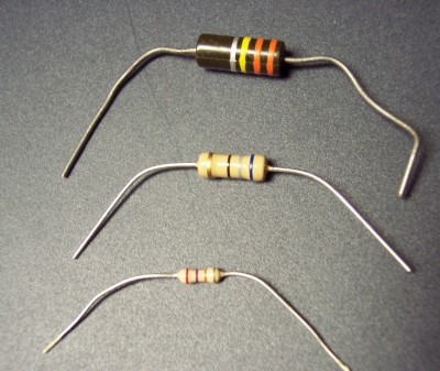
Picture 3.1 Example Resistors.
Chapter 3 Failure Modes.
3.1 Generalized Failure Modes.
3.2 Electrolytic Capacitors.
Chapter 3.
Failure Modes.
It is possible to spend an entire career studying the failure modes of electronic components. In this chapter we will cover only the electrical characteristics of failed components.Back to Fun with Transistors.
Back to Fun with Tubes."
Back to Table of Contents.
Back to top.
3.1 Generalized Failure Modes.
Electronic components usually fail in a specific way. That is a good thing; it makes the job of troubleshooting easier than it would be if components failed in random ways.For example, capacitors almost always fail shorted while resistors almost never fail shorted. If there is a parallel combination of a resistor and a capacitor and the combination is found to be shorted, we can be almost certain that the capacitor is at fault.
The word "almost" appears in these statements because we are dealing with probability and there are no absolute certainties, only very high probabilities.
Resistors.
Picture 3.1 Example Resistors.
In the photo above the top resistor is a 330 k ohm 10% 1 watt carbon composition, the middle one is a 68 ohm 5% 1 watt carbon film, and at the bottom is a 27 k ohm 5% 1/4 watt carbon film resistor.Components fail in the way they do because of the way they are constructed. Resistors are constructed in two main ways. One type is known as carbon composition. It is made by mixing up a concoction of finely powdered graphite, an equally finely powdered insulating material and some kind of glue. The brew is molded into a small cylinder and dried. The lead is in the form of a nail as shown in Figure 3.1.
Figure 3.1 Construction of Carbon Composition Resistor.
For a verbal description click here.
The two leads are placed in contact with the ends of the cylinder and the assembly is encased in molded plastic. Color code bands are painted on the finished resistor. The force exerted by the lead's "head" against the end of the cylinder is the only connection between them. I have seen such resistors in which it was possible to rotate the resistor body on its leads. Needless to say the amplifier was very noisy especially when shaken.The other type is carbon film or metal film. They are made by coating a ceramic or plastic cylinder with graphite or metal. Metal cups are placed over the ends of the cylinder and crimped in place to make good electrical contact with the film. The cups have leads attached as shown in figure 3.2.
Figure 3.2 Construction of Film Resistor.
For a verbal description click here.
The assembly is then placed in a lathe where a laser starts cutting a helical path in the conductive coating turning it into a coil of conductor surrounding the insulating cylinder. The resistance is being measured continuously and when it reaches the desired value the laser is turned off and the resistor goes on to have its body encased in plastic. Color bands are then painted on. The end contacts are what gives these resistors their characteristic shape.Carbon composition resistors can be reduced in value by excessive heat which turns some of the glue from the original mix into carbon. I have seen a 100 ohm resistor be reduced to 11 ohms by being burned to a crisp. However, this is rare. They usually increase in value with age and can totally fail open or become noisy as described above.
Film resistors are much more reliable because of the crimped connections. They hold their original value very well and rarely fail spontaneously. They can even remain very close to their value after some serious overheating.
Capacitors.
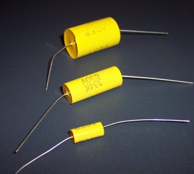
Picture 3.3 Example Capacitors.
Capacitors are constructed of two thin pieces of metal foil with a very thin insulator between them as shown in Figure 3.3.
Figure 3.3 Construction of Plastic Film Capacitor.
For a verbal description click here.
Here the most likely failure is in the insulator, which will allow the two metal foils to touch, causing a short.It is possible for the connection between the foil and the wire (which runs through the case to the outside world) to come loose causing an open circuit, but this is a low probability occurrence.
Capacitors are constructed by starting with a long strip of a sandwich consisting of a layer of aluminum foil, a thin film of plastic, another layer of foil and another layer of plastic film. The strip is rolled up to form a cylinder. The sandwich is made so that one of the foils sticks out slightly on one side and the other sticks out the other. Thus, the two foils are exposed one on each end. The connecting lead is made to resemble a nail. The head of the nail, where the hammer would hit it, is spot welded to the foil on the end of the cylinder. The whole thing is encased in plastic.
Transformers, Chokes, and other coils.
Components which consist of a coil of wire such as transformers, inductors and TV deflection yokes have two main failure modes. The wire can break or burn in two (probably due to a manufacturing flaw) causing an open circuit or the insulation on the wire can fail causing a short.An open is quite easy to diagnose. Testing with an ohmmeter will show infinity on the defective winding.
A short may be a little more subtle. Unless the transformer is absolutely cooked the short is likely to be over one turn. One turn out of hundreds is not enough change in resistance to show up on a DC resistance measurement. In the case of a transformer when power is applied a high current will flow and if the fuse doesn't blow the transformer will get hot very quickly and emit a bubbling sound as wax or varnish inside begins to boil. There is no saving such a transformer. It must be replaced. In the case of a choke its inductance value will be reduced to a small fraction of its normal value. An inductance bridge or meter will be required to diagnose such a defect. In the case of a TV deflection yoke the picture will b askew and either the vertical or horizontal output tube will be overheating due to too much current. Possibly to the point of having its plate glowing red. The coil of a DC relay may not be affected by a shorted turn and may operate for decades undetected. On the other hand a shorted turn in the coil of an AC relay will cause it to draw too much current and also prevent enough magnetic field from being developed to close the contacts. In a few cases it may be possible to disassemble the relay and replace the coil. In most cases the entire relay must be replaced.
Semiconductors.
When semiconductor devices fail spontaneously, which is rare, they don't fail in a binary manner. What usually happens is that a lead which was welded to the crystal in the factory comes loose. Because there is no force to move the lead away from the crystal they will remain in contact, sort of. If the device is a transistor in a radio or amplifier the result will be static in the speaker. Shaking or slapping the radio or amplifier may or may not affect the crackling sound.In a radio the bad transistor can usually be found by half splitting as explained in chapter 4 although you must be aware that changing impedance as the contact makes and breaks will change the load on the previous stage and cause the defect to appear at the output of the stage previous to the one with the defective transistor.
In a stereo amplifier the presence of negative feedback will cause the static to propagate around the entire feedback loop and no amount of signal tracing will locate the defective device. In such cases the only solution is to unsolder a component such as a resistor to open the feedback loop but BEWARE! In many stereo amplifiers the same feedback loop serves to stabilize the DC operating point as well as provide AC feedback for performance improvement. Opening such a loop will usually result in the output of the amplifier locking to one of the power supply rails. This could damage the amplifier giving you more defective parts to find and replace. In such a case try temporarily replacing the feedback resistor with two resistors in series, each half the value of the original. If there was a capacitor in parallel with the resistor temporarily remove it. Connect a capacitor from the junction of the two resistors to ground. The capacitor to ground should be of such a value that it forms a 10 second time constant with the parallel equivalent resistance of the two resistors. This allows the DC feedback to remain effective while the AC feedback is removed. It should now be possible to find the source of the noise by signal tracing.
When a semiconductor device fails as a result of some other component failure the semiconductor was destroyed by heat. When the silicon crystal is heated it eventually gets hot enough to melt. This results in a short between all leads of the device. As noted elsewhere in this text, the short can result in the current being so high that the wire leads or the crystal itself are burned away leaving an open circuit. Open is a secondary failure mode.
On rare occasions the semiconductor crystal will get just hot enough for the doping impurities to defuse in the crystal which will change the characteristics of the device. The usual result is that the breakdown voltage of junctions is reduced. Meaning that a transistor will no longer operate at the applied collector voltage or a diode will conduct somewhat in the reverse direction. If this rare failure mode occurs it may be very hard to find because it is so rare and is not expected. If the early breakdown does not finish off the device it may turn into a real dog. Transistors and diodes which appear to be good in an out of circuit test may still not work in the circuit.
Summary of Failure modes.
The failure modes of the most common components are summarized in table 3.1.Table 3.1.
Summary of Failure Modes of a Few Electronic Components.
Component High Probability
Failure Mode(s)Low Probability
Failure Mode(s)Resistor Open
Resistance value
increasedResistance value
decreasedCapacitor,
FilmShorted
Leaky (Effective
parallel resistance
too low)Open Capacitor,
ElectrolyticShorted
Leaky (Effective
parallel resistance
too low)
Effective series
resistance increased
OpenInductor
Transformer
Relay coil
Deflection
yokeOpen
ShortedDiode Shorted Open Transistor Base to Emitter
short
Base to Collector
short
Everything to
everything shortIntermittently
noisy
OpenOperational
AmplifierOutput shorted to
one power supply railLow input
resistanceDigital IC Output shorted to
ground or V+Vacuum
TubeLow cathode
emission, (weak)
Shorts between
elementsHeater or
filament open
Cascading Failures.
Failures can cascade. Consider the case of the simple power supply of figure 3.4. This is a typical circuit of those power supplies which are in plastic cases with AC plug prongs on them. These are often called "wall mounted" power supplies or wall warts. You will note that there are no fuses in the circuit.

Figure 3.4 Schematic of Wall Wart.
For a verbal description click here.
Most recently made wall warts have some sort of fuse built into the transformer. This may be a current sensing or temperature sensing fuse. In either case it is a one time only operation and if it is burned out the entire wall wart must be replaced. The cost of obtaining a replacement transformer will most likely be about equal to the cost of a new wall wart.If you have to repair a very old wall wart that has an unusual voltage making it impossible to replace you may have to saw it open and work on it. If so the paragraphs below will apply. These paragraphs will also apply to a power supply that is built with discrete components.
The failure could begin with a shorted filter capacitor. This causes the diodes in the bridge rectifier to overheat and eventually one or more will become shorted. This puts a very heavy load on the transformer causing it to overheat and develop shorted turns. This causes the transformer to draw even more current and get even hotter. The user may not know that anything is wrong until he or she smells the transformer burning and by then it is too late.
It is very common for failures to cascade in this manner. The first fault you find may be a symptom rather than a cause.
In the example of the power supply above, suppose that the transformer had been protected by a fuse. In that case the diodes would have likely shorted out anyway because of one of Murphy's laws, "An expensive semiconductor device protected by a fuse will protect the fuse by burning out first." Therefore, when the power supply comes to your service bench it will have a shorted filter capacitor and one or more shorted diodes. If you replace the faulty diodes and the fuse and apply power you will just burn out some more diodes and another fuse.
The table lists open semiconductors as a low probability occurrence. You may find open semiconductors in the normal course of service work. This most likely is a secondary failure mode.
In some circuits if a transistor shorts, an excessive amount of current can flow. This excessive current can cause the fine wires inside the transistor to melt, thus producing an open circuit. First the transistor shorts and second it burns open. That is a secondary failure mode.
Secondary failure modes are hard to predict in general because they depend on the circuit. In general if a secondary failure occurs, other components will be taken out as well.
The matter of secondary failures and cascading failures will be dealt with as they come up in specific circuits.
Back to Fun with Transistors.
Back to Fun with Tubes."
Back to Table of Contents.
Back to top.
3.2 Electrolytic Capacitors.

Picture 3.5 3 Electrolytic Capacitors.
Electrolytic capacitors are unique enough to warrant a section of their own. In the picture above top is a two section can electrolytic. The negative end of both capacitors is connected to the can and the positive ends are brought out to the two large lugs. A capacitor of this type mounts in a special cutout made in the chassis in a factory or more often mounts on a mounting plate which has slots for the four smaller lugs that are around the edge of the bottom of the can. These capacitors are made with up to 4 separate capacitors in one unit.Next is a single 450 volt capacitor that is used in tube circuits. Below that is a small 25 volt capacitor that is found in transistor circuits.
All of these capacitors have positive and negative terminals. Reversing the polarity can be catastrophic.
Electrolytic capacitors are an exception to the rule that capacitors rarely fail open. They are made similarly to conventional capacitors as described above but the insulator is a porous paper instead of plastic film. The paper is impregnated with an electrolyte usually an acid. During the manufacturing process each capacitor is connected to a current source. This causes a layer of aluminum oxide to form on the positive foil. As the voltage increases the oxide layer becomes thicker and the process is terminated when the voltage reaches about 1.5 times the intended working voltage. This process is known as forming the capacitor.
The paper is not the insulator, dielectric, of the capacitor, the oxide layer is. The aluminum foil is the positive plate, the oxide layer is the insulator and the electrolyte in the paper is the negative plate.
A common failure mode in equipment which has never worked is for the capacitor to be reverse polarized. Electrolytic capacitors are used in power supplies. If someone connects one backwards the capacitor will conduct a substantial direct current. This current heats up the capacitor interior and when it gets hot enough the water in the electrolyte turns to steam, pressure builds up inside the container and the capacitor literally explodes. The minimum sound is like a fire cracker but if the capacitor is large it can range up to a cherry bomb or a silver salute.
Other than the above electrolytic capacitors don't fail anymore often than plastic film capacitors as long as the equipment is in continuous use. Defective electrolytics are most often encountered by those who restore vintage electronics.
Electrolytics made 50 or more years ago probably weren't as well sealed as modern ones. They can dry out. With most of the water gone from the electrolyte the capacitance is reduced to a small fraction of its original value. Such capacitors are open and have to be replaced.
Another very common failure mode for electrolytic capacitors in vintage electronics equipment which has not been turned on for decades is to become unformed. The oxide layer has become very thin. If treated with care such capacitors can be reformed outside of the factory. The thing you must not do with vintage equipment is turn it on. The capacitors in the power supply will explode if the primary fuse doesn't blow first. Considerable damage can be done to other components, some of them difficult to find. More details can be found in a later chapter devoted to trouble shooting and restoring vintage electronics.
WARNING! Be sure to take the special precautions outlined below or you will wind up with a burned out meter. If you just connect the meter in series with a capacitor across a power supply, when the supply is turned on the charging current of the capacitor will be as much as an ampere and a sensitive milli amp or micro amp meter will be burned out.
The empirical formulas below tell you when to discard an electrolytic capacitor. In order to actually measure the leakage currents without destroying your meter here is what to do.
- Connect a short across your meter and set it to a high current range.
- Connect the meter in series with the capacitor you want to test.
- Connect the combination across the power supply.
- Turn on the power supply.
- wait for 1 minute.
- Remove the short from the meter.
- Start switching to lower ranges until you can read the leakage current.
- Write down the value.
- place the short back on the meter.
- Turn off the power supply.
- Discharge the capacitor by connecting a 10 k ohm 1 watt resistor across it for as long as it takes for the voltage to fall below 5 volts.
- Disconnect everything.
- Apply the formulas below to determine the state of your capacitor.
The current you measured above is termed the leakage current. In normal operation it does no harm but if it becomes too large the capacitor can fail violently as described above. A set of formulas which give the approximate leakage current are given below.
ILMin = Sqrt(VC)/5 IL is the leakage current, V is the rated voltage and C is the rated capacitance of the capacitor.ILMax = Sqrt(VC)/2
ILWorst Case = Sqrt(VC)*6
Note: Those familiar with basic electricity will remember that CV = Q, where Q is the charge stored in Coulombs. This may be just a coincidence. I can't readily see how the square root of charge gives the leakage current. Dimensionally it gives meters times the square root of Newtons. This must be an empirical equation. It came from a capacitor manufacturer which is no longer in business.The leakage current IL values for minimum, maximum, and worst case, are for newly manufactured capacitors. But if an older capacitor fails to reform to a current less than the worst case it should probably be discarded. Detailed reforming instructions will be given in the chapter on vintage equipment.
Here is an alternative method for testing an electrolytic capacitor using a voltmeter instead of a sensitive current meter.
- Connect the capacitor in series with a resistor and the series combination across a power supply which is set to a voltage equal to the working voltage of the capacitor.
- Set a voltmeter to a range just higher than the power supply voltage.
- Connect the meter across the resistor. Start with a resistor having the value R = V / IL Where R is the resistance of the resistor for the initial test and IL is the expected leakage current from the above equations.
- When the meter reading stops increasing turn off the power supply and discharge the capacitor.
- Substitute a resistor having the value R = V / (10 x IL) If the capacitor is good the meter reading will rise to 90% of the power supply voltage.
The above test method will also serve to reform an electrolytic capacitor which has become unformed from prolonged disuse.
Effective Series Resistance, ESR.
Another common defect of electrolytic capacitors is for the effective series resistance to increase. All capacitors have some series resistance. It is as though there is a small resistor inside the case along with the capacitor. This resistor is in series. In film capacitors this resistance is very small being typically a fraction of an ohm. But in electrolytic capacitors the ESR can be significant. The usual cause is drying out of the electrolyte. A capacitor which is 20 years old may be slightly dried out causing an ESR of a few ohms. Depending on the application such a capacitor may not give any indication of trouble. A capacitor which is 50 years old may be so dried out that its ESR is so high that it can no longer effectively bypass a cathode resistor or act as a filter in a power supply. It may show good on a capacitor tester and you may be able to measure its capacitance with a bridge but it just doesn't work right. Other 50 year old capacitors may be completely dried out and are effectively open. The latter are usually enclosed in a cardboard tube and sealed with wax as opposed to being in metal cans. These wax sealed capacitors were used in all American 5 radios and give the symptom of a loud hum in the speaker after the tubes warm up.Some testers and many bridges measure the D (dissipation) factor along with the capacitance. The dissipation factor is defined as
D = Rs / Xc Where Rs is the effective series resistance, and Xc is the reactance of the capacitor calculated at the test frequency. Therefore,Rs = D Xc Substituting for Xc gives,Rs = D / (2 pi f C) Where pi = 3.14159, f is the test frequency of the meter or bridge, and C is the capacitance in farads, not microfarads.I know of no simple setup that will reliably measure ESR. One way might be to run up the frequency until Xc is less than an ohm then apply a current and measure the voltage. The problem is that the frequency may be so much higher than the normal operating frequency as to render the results meaningless. Substituting a known good capacitor is probably the only way to diagnose high ESR.
Back to Fun with Transistors.
Back to Fun with Tubes."
Back to Table of Contents.
Back to top.