Figure 9.1 Basic Block Diagram of a Frequency Counter.
For a verbal description click here.
Chapter 9 Digital Instruments.
9.1 Frequency Counter.
9.2 Digital Multimeter.
9.3 Frequency Synthesizer.
9.4 Problems.
9.5 Answers to Problems.
Chapter 9
Digital Instruments.
If you were asked to name something in which digital circuits are used you would likely answer "a digital computer". Combinational logic is certainly used in a digital computer. The subject of computers is one which can occupy a course of its own. There is not time or space here to study computers. There are certain laboratory instruments which employ digital circuitry but which are not computers. These instruments do not require connection to a computer for operation and so are called "stand alone" digital instruments. Three examples which we will look at in this chapter are the frequency counter, the digital multimeter and the frequency synthesizer.Back to Fun with Transistors.
Back to Fun with Tubes."
Back to Table of Contents.
Back to top.
9.1 Frequency Counter.
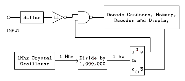
Figure 9.1 is the block diagram of a basic frequency counter. This circuit is not intended as a construction project. If you were inclined to build a frequency counter, you would need more details. This circuit contains all of the essential parts for understanding the operation of a frequency counter.
Figure 9.1 Basic Block Diagram of a Frequency Counter.
For a verbal description click here.
The input feeds to a buffer which is a circuit with a high input impedance and a low output impedance. This is an analog amplifier circuit which must have a bandwidth equal to that of the counter circuits. The buffer may or may not have a voltage gain greater than unity.After the input signal is buffered and possibly amplified, it is necessary to form it into a succession of logic highs and lows to be counted by the BCD counters. What must be done is to form the input signal into a square wave which has a low level of 0 volts and a high level of 5 volts. A comparator might be used for this purpose but there is a problem. Noise is always present. A comparator will amplify the noise and instead of a clean square wave its output would be a wave which looks to be a square wave but a closer look reveals that instead of one transition, the voltage makes several jumps from 0 to 5 volts and back again, before settling down on one or the other. Logic circuits respond so fast that they would count these extra transitions as if they were cycles of the input signal. The result would be that the counter would read several times the actual frequency.
The device which is required is called a Schmitt trigger. To explain what a Schmitt trigger does let us look at a specific example, namely the TTL Schmitt trigger. The specifications for such a circuit give its "positive-going trigger voltage VT+" as 1.7 volts and its "negative-going trigger voltage VT-" of 0.9 volts. Suppose the input voltage starts out at zero. Because the circuit is an inverter, the output will be a logic high. As the input voltage is slowly increased, nothing happens until the input voltage reaches 1.7 volts. At this input voltage, the output suddenly switches (in about 20 ns) to a logic low. Further increases in the input voltage have no additional effect. As the voltage is slowly decreased the 1.7 volt point is crossed without anything happening. Nothing happens until the input voltage gets down to 0.9 volts at which point the output switches to a logic 1. As long as the peak-to-peak amplitude of the noise is less than 0.8 volts the output of the Schmitt trigger will switch only once for each slope of the input wave. The resulting output is a clean square wave.
There are also Schmitt triggers in the CMOS logic family. For these VT+ = 2/3 VCC and VT- = 1/3 VCC. The difference between VT+ and VT- is called the hysteresis of the Schmitt trigger. If the input voltage is between VT+ and VT- the state of the output depends on whether the voltage came down from above or up from below. In other words the state depends on the history of the circuit. Hence the name hysteresis.
CMOS has a larger hysteresis than TTL and, therefore, greater immunity to noise. However, CMOS is not as fast as TTL, which means that it will not count as high a frequency as will TTL.
The next item in the diagram is a NAND gate. Now a NAND gate is just a NAND gate but the other signal to the gate requires some explanation. First of all remember that A NAND 0 = 1 and A NAND 1 = A. Inverting the signal will not change its frequency. When the signal from the flip-flop is 1 the input signal is passed to the counter circuits and when the signal from the flip-flop is 0 the gate is closed and the input signal is not passed to the counter circuits.
The 1 MHz quartz crystal oscillator gives a very precise frequency. This frequency is divided by 1,000,000 to give a very precise 1 hertz frequency. The flip-flop has its J and K inputs high and so will change states on every negative-going edge of the clock input. Thus the Q output will be high for 1 second and low for 1 second. The counter circuits count the total number of cycles and the gate is open for precisely 1 second; so the counter is indicating the number of cycles per second, which is the frequency in hertz.
The not Q output of the flip-flop is fed to the counter circuits and signals when to load the count into the display memory and reset the counter to zero. The not Q signal is not used directly for strobe and reset. It is used to trigger delay circuits, one shots, which perform the strobe and reset in the proper time sequence.
The time that the gate is open does not have to be 1 second. It could be 0.1 second or 0.01 second or anything else. Most counters have a switch to allow the user to select the desired gate time. The proper decimal point lights up in the display along with an additional indicator to tell the user whether the number should be interpreted as hertz, kilohertz or megahertz.
The reasons for having different gate times are resolution and sample rate. If a 1 second gate time is used the reading will be to the nearest hertz which is the resolution of the reading. In some measurements the user may not desire to know the frequency to such precision. The frequency source may be so unstable that the units of hertz are a random number generator. In such cases it is usual to use a shorter gate time to get rid of the insignificant digits of the reading. A shorter gate time gives faster readings. A gate time of 10 seconds gives 0.1 hertz resolution but gives a reading every 20 seconds. A 1 second gate gives a reading every 2 seconds and a gate time of 0.1 second gives 5 readings per second. The gate time chosen depends on how much precision is desired and how impatient the user is.
Back to Fun with Transistors.
Back to Fun with Tubes."
Back to Table of Contents.
Back to top.
9.2 Digital Multimeter.
The digital multimeter (DMM) uses a combination of digital and analog circuits to measure voltage, current and resistance with great accuracy. All of the individual circuits have been discussed earlier in this text.The basic measurement circuit of a digital multimeter is the dual slope integrator, which is a voltage measuring device. In most DMMs (digital multimeters) the basic voltmeter circuit has a full-scale range of 0.2 volts (200 millivolts). Voltage dividers are used to give additional ranges of 2, 20, 200 and 2,000 volts full-scale.
For measuring current a series of shunt resistors is connected across the basic voltmeter. The usual ranges are 200 uA, 2 mA, 20 mA, 200 mA and 2 A. Some DMMs have a 20 amp range as well.
AC voltage and current may be measured using most DMMs. An absolute value amplifier is used to convert the basic DC voltmeter to a basic AC voltmeter. An RC network is used as an averaging circuit and so the voltmeter is an average responding voltmeter. The gain of the amplifier is adjusted so the meter will indicate RMS if the input is a sine wave.
More recent DMMs employ a true RMS circuit to convert the AC to DC. When using such meters the reading will always be true RMS regardless of the wave form.
In order to measure resistance the basic DC voltmeter is used to measure the voltage across the unknown resistor while a constant current source supplies current to the unknown. The usual ohmmeter ranges are 200 ohms, 2 k ohms, 20 k ohms, 200 k ohms, 2 M ohms and 20 M ohms. For each of these ranges the value of the current source will be 1 mA, 100 uA, 10 uA, 1 uA, 100 nA and 10 nA, respectively.
Back to Fun with Transistors.
Back to Fun with Tubes."
Back to Table of Contents.
Back to top.
9.3 Frequency Synthesizer.
Some types of laboratory measurements require a very stable and accurate frequency. Quartz crystal oscillators provide very stable and accurate frequencies but the frequency is determined when the crystal is manufactured and, if it is desired to change the frequency, a new crystal must be ordered.There are various oscillator circuits whose frequencies can be varied by means of variable resistors, capacitors, or inductors, but variable frequency oscillators (VFOs) are not as stable over time as quartz crystals. If accurate frequency settings are desired, a frequency counter must be used in conjunction with the VFO.
The use of a frequency counter solves only half of the problem. VFOs drift in frequency. Drift is caused by changes in temperature and humidity, component aging, minute changes in the power supply voltage (no regulator is ever perfect) and other factors which seem to defy scientific explanation. Put a VFO in an environmental chamber, let it warm up for weeks or even months, operate it from an ultra precision power supply and it will never stop drifting.
Until the age of modern electronics the choice had to be either a fixed frequency and stable crystal oscillator or an adjustable frequency and drifting VFO. A circuit known as the frequency synthesizer is capable of combining the frequency agility of a VFO with the stability of a quartz crystal.
First of all a frequency synthesizer is not a musical instrument. A music synthesizer is comprised of an entirely different set of circuits. A frequency synthesizer can produce the musical scale but it can also produce any frequency in between the notes. The basic block diagram of a frequency synthesizer is shown in Figure 9.2.
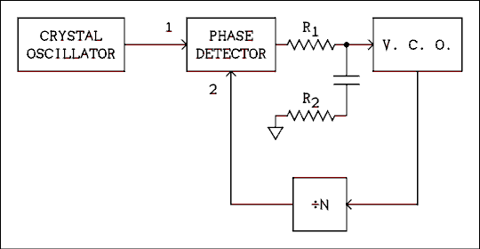
Figure 9.2 Basic Block Diagram of a Frequency Synthesizer.
For a verbal description click here.
The circuit as drawn may also go by the name phase- locked loop. The V.C.O. is a voltage controlled oscillator. If the input voltage goes positive, the frequency of the V.C.O. will go up; if the input voltage goes negative the frequency will decrease. The phase detector has changed in recent years. It is now a digital circuit which can detect large frequency differences as well as small phase differences. If the frequency of input 2 is higher than the frequency of input 1, the output voltage of the detector goes negative. If the frequency of input 2 is lower than the frequency of input 1, the output voltage goes positive.If the frequency of the V.C.O. is lower than it should be, the frequency of input 2 to the phase detector will be lower than the frequency of input 1 (the crystal oscillator) and the output voltage of the phase detector will go positive. This positive-going voltage will be applied to the V.C.O., which will cause its frequency to increase. The circuit will soon find an equilibrium point at which the frequency at input 2 ( fVCO / N ) is equal to the frequency of the crystal oscillator. After the frequency is correct, the circuit goes to work on the phase angle. If the phase at input 2 is leading the phase at input 1, the output of the phase detector will go slightly negative and the phase error will be corrected to zero.
The unfiltered output of the phase detector is a series of positive or negative-going pulses whose width is proportional to the phase difference between the two input signals. If the phase angle could come to exactly zero the output of the phase detector would be an open circuit all of the time. (The output has a low impedance during the pulses but is an open circuit between pulses.) Nothing in this world is ever exact or perfect. There will always be some AC output from the phase detector. The RC network which is connected between the phase detector and the V.C.O. serves the purpose of filtering out most of the AC component of the output of the phase detector.
The filter requires two resistors in order to make the loop stable. An unstable loop will cause the frequency of the V.C.O. to jump around instead of locking on to the frequency of the crystal oscillator. Typical values for R1 and R2 are 1 M ohm and 100 k ohms, respectively. The value of the capacitor may range from 0.01 uf to 10 uf. If a given loop is unstable, R2 should be temporarily replaced by a resistor substitution box and the value "played with" until the loop is stable. The capacitor should be as large as possible consistent with the minimum lock-in time of the loop.
The frequencies at inputs 1 and 2 of the phase detector will always be equal. Therefore, if the frequency of the crystal oscillator is fR and the frequency of the V.C.O. is fO, then the frequency of the V.C.O. is given by
fO = N fR (9.1) The divide by N block is a variable modulus counter which is usually programmed by means of thumb-wheel switches. Because N is restricted to integer values, the smallest step in frequency which is possible is the frequency which is applied to input 1 of the phase detector. The smallest step is the resolution of the frequency synthesizer.If a crystal cannot be obtained in a low enough frequency for the desired resolution the output of the oscillator may be divided by L as shown in Figure 9.3. The output frequency is now given by
fO = fR N / L (9.2) The resolution is now fR / L.
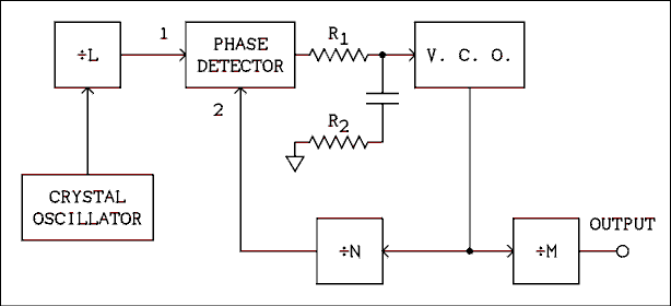
Figure 9.3 Frequency Synthesizer Circuit.
For a verbal description click here.
If the resolution is to be less than one hertz the input to the phase detector must also be less than 1 hertz. The required value of C in the loop filter is so large that it takes a very long time for the loop to lock in again after the value of N has been changed. Another way to get fractional hertz changes is to insert yet another divider in the circuit also shown in Figure 9.3. The divide by M circuit is a fixed modulus divider which divides the frequency of the V.C.O. before it is delivered to the output terminal. The output frequency is given by,fO = fR N / (L M) (9.3) The resolution is fR / (L M).Example 9.1.
In a synthesizer similar to Figure 9.3 the frequency of the crystal oscillator is 100 kHz, L = 5,000, M = 400 and 10 is less than N is less than 10,000. What are (a) the frequency range and resolution of the output and (b) the frequency range of the V.C.O.?Solution:
The frequency at input 1 of the phase detector is 100 kHz / 5,000 = 20 Hz. The frequency at input 2 is also 20 Hz and so the frequency of the V.C.O. ranges from 10 x 20 Hz to 10,000 x 20 Hz = 200 Hz to 200 khz, which is the answer to part (b). The output frequency is the V.C.O. frequency divided by 400, which is 200 Hz / 400 to 200 kHz / 400 = 0.5 Hz to 500 hz, which is the first part of (a). The smallest frequency step for the V.C.O. is 20 Hz. The smallest step for the output is 20 Hz / 400 = 0.05 hz.The output will go from 0.5 Hz to 500 Hz in 0.05 Hz steps. The V.C.O. must be capable of being tuned from 200 Hz to 200 kHz.
Back to Fun with Transistors.
Back to Fun with Tubes."
Back to Table of Contents.
Back to top.
9.4 Problems.
- A frequency counter has an 8 digit display and any one of the decimal points can be illuminated. If the gate time is 100 us and the readout is in MHz, where should the decimal point be placed. Number the digits from left to right and state which two the decimal point is between.
- A DMM uses the 200 mV range to measure current. What resistor should be used as a shunt on the 20 mA range?
- A DMM uses the 2 volt range for the 200 ohm range. What is the constant current for this range?
- In a synthesizer similar to Figure 9.3 the frequency of the crystal oscillator is 2 MHz, L = 40,000, M = 5,000 and 45,000 is less than N is less than 75,000. What are (a) the frequency range of the V.C.O and (b) the frequency range and resolution of the output?
Back to Fun with Transistors.
Back to Fun with Tubes."
Back to Table of Contents.
Back to top.
9.5 Answers to Problems.
- Between 6 and 7.
- 10 ohms.
- 10 mA.
- (a) 2.25 to 3.75 MHz. (b) 450 to 750 Hz in 0.01 Hz steps.
Back to Fun with Transistors.
Back to Fun with Tubes."
Back to Table of Contents.
Back to top.