ALAN TURING, working at Bletchley Park, had
formed the opinion that the solution (to
'Enigma') would not be found by creating a
machine that replicated sixty Enigmas. His idea
was to use rotors and wires that would simulate a
series of Enigma rotors and pass an electrical
current from one rotor to the next. However,
rather than looking for the one correct rotor
setting based on the indicators, as the Polish
Bomba did, Turing’s machine would look for
all the settings and disregard those that were
incorrect. For example, if the assumed letter was
"B" and the corresponding cipher letter was "N,"
Turing’s test register ignored any results
that did not allow the electrical current to pass
from "B" to "N." By disproving several thousand
rotor settings, those remaining were possibly
correct settings.
|
|
|
Gordon Welchman, a mathematician and
Fellow of Sidney Sussex College, Cambridge, was
meanwhile working on another facet of the Enigma,
the plugboard. Because the plugboard uses a cable
to connect one letter to another, it
automatically connects the second letter back
with the first. If A is plugged into E, E is also
plugged into A. With this knowledge, 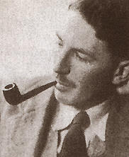 Gordon
Welchman, who had already redeveloped Zygalskis
perforated sheets for five rotors, designed a
diagonal board to reduce the complexities posed
by the Enigma’s plugboard. Gordon
Welchman, who had already redeveloped Zygalskis
perforated sheets for five rotors, designed a
diagonal board to reduce the complexities posed
by the Enigma’s plugboard.
With Welchman's board combined with
Turing’s machine, the number of possible
rotor settings would decrease from thousands to
just a few. Harold "Doc" Keen, an engineer at
British Tabulating Machines (BTM) converted
Turing and Welchman’s ideas into working
machines, but It took until August 1940 for the
first operational machine (called a
‘bombe’) to be installed at Bletchley
Park.
|
|
The construction of the first
‘Bombe’ by BTM took two months but
eventually the firm was able to produce one
machine each week. A total of around two hundred
Bombes for use in England were produced during
the war years. As well as at Bletchley Park, some
were installed at units located in nearby
Wavendon House, Whaddon Hall, Gayhurst House,
Adstock Manor, a farm at Drayton Parslow and,
reportedly, at Woburn Abbey, home of the Duke of
Bedford.
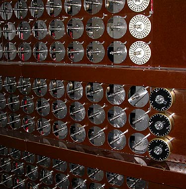
A basic bombe weighed a ton and was
over six feet high, seven feet long, and two feet
wide. It had thirty-six sets of three rotors.
Within each set, the top drum represented the
left rotor on Enigma; the middle, the centre
rotor, and the bottom, the right rotor. The Bombe
produced settings which attempted to complete an
electrical circuit through each of the test
registers and through the diagonal board. Most of
the settings could not complete the path
correctly and these were discarded. Those that
succeeded caused the machine to stop and a
reading of the rotor settings was taken.
When a correct setting had been
recorded, the operators (who were mainly members
of the Women’s Royal Naval Service or
‘Wrens’) moved on to the next
message. It took ten minutes for the Wrens to
change the wheel order for the next run and
further half-hour or more to set up the new
connections.
|
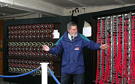
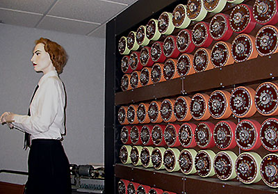
One of the excellent guides at Bletchley Park
describing Alan Turing's 'Bombe'.
(Right)
The
'Bombe' models are situated in the heavily
reinforced brick, steel and concrete Hut 11.
The walls are two feet thick and
contain steel girders at two feet intervals. The
ceiling, just eight feet above the ground and
supported by fifteen-inch girders cemented into
the concrete floor, is made up of eighteen-inch
inch steel girders embedded in concrete and
further supported by twelve-inch steel girders
(visible in the photograph).
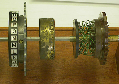
The front view of the rotors.
(Above, and right, to the left of the
picture)
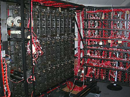
The connecting looms at the rear of the bombe.
(Right, on the right-hand side of the picture, and
below, on a bombe under reconstruction)
|
|
The front view of the rotors
on a bombe presently under reconstruction
(left).
|

|

|
|

