
If you are a telecommunications service provider and, having just received your license to provide telephone services in an area, you have set up you first switch. As are a wise person, you would not like to build up a comprehensive access network unless you are sure to the demand. You like to do with the bare minimum till the revenues start flowing in. What is the minimum requirement between the user equipment and your switch? Well you don't need a lot. You just need to link the customer premises equipment(CPE) to you switch with a pair of copper conductors.

Though the above set-up gives a workable solution in practice it would give some problems to you, the service provider. To say some would actually be an understatement. It gives problems in all the areas viz. Planning, Construction and Maintenance! Not to mention the increased cost and time of carrying out the work.
The planner of such a network does not have much choice. In fact he does not have much of role in such a network. Since each pair is laid on demand he does not provide for future. There is no flexibility in the network. If another customer next door to the existing customer asks for a connection then another pair has to be laid right from the exchange to the customer. All this leads to repeated infructuous work and increases material and labour cost.
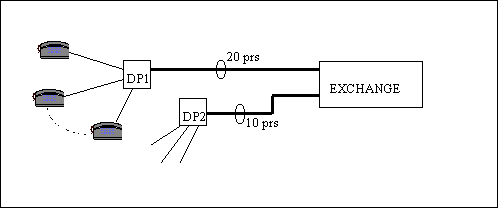
If we lay slightly bigger cables, say 10 or 20 pair cables up to the vicinity of a a group of tenancies, then any nearby subscriber can be given service much faster by allocating one of the spare pairs. The multi-pair cable is terminated in a box which is called a distribution point(DP) as the pairs are distributed to subscribers from here.

The way we grouped several subscribers into DPs we could group a number of DPs and serve them with
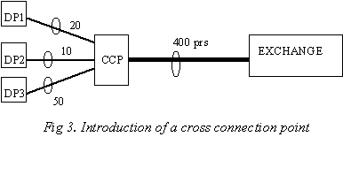
a common cable. We need to set up another point, a cross connection point, upto which we would bring a still larger cable
than we brought to the DP and serve a number of DPs from that point. Let's see how it will look.

Now there is one larger cable going to the the crossconnection point(CCP). This CCP provides the capability of connecting any of the pairs of this cable to any of the DPs, in its area, thus offering great flexibility in pair management For this reason a CCP is also called a flexibility point. Introduction of a CCPcould be called a revolutionary change in the access network. A common name for this cross connection point is cabinet. An urban network would have a number of cabinets each serving a number of DPs. The cabinet area may have hunreds of customers while the DP areas would have tens of customers.
On a pessimistic note one could argue that now we have big cables going from the exchange upto the cabinets. We could for example have a 1200 pair cable going to one cabinet and say a 800 pair going to the other. Now if we have exhausted all the pairs of one of them then would it be possible to use pairs from the other for the customers in the exhausted area? Again a case of pairs being available in the network but not at the right place!
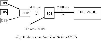
To make a larger part of the cable common to many more subscribers we could add one more cross connection point.
Is'nt this going too far? How many cross connection points can we possibly have between the exchange and the DP?
Theoretically as many as the designer wants but going by the international norms upto two such cross-connection
points are used. If we did this the network would look like this:

The above structure has all the rudiments of the real-life access network. The first CCP from the exchange is called the Primary Cross-connection Point(PCP) or the cabinet and the cable linking the PCP to the Exchange is known as the Primary cable. The network of all the cabinets and the primary cables is referred to as primary network. The second CCP is known as the Secondary Cross-connection Point(SCP) or the pillar and the cables linking pillars to the cabinet are known as secondary cable. The cables linking DPs to the SCP are known as Distribution cables and together the distribution cables, DPs and other related infrastructure form the distribution network.
So what are the advantages of having cabinets (and possibly pillars) in the network instead of having direct pairs from the exchange to the customers? We surely have not incurred the extra cost of installing cabinets and pillars for fun! Let's enumerate some of these..
Click to read more on structure and components of access network...
Or you could study one of these..
1. Introduction to telecommunication networks
3. Forecasting
4. Planning access networks
5. New technologies in the access network