
This part talks about a document of the NASA dealing with the guidance and navigation of the lunar module.
Link to this document
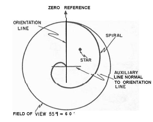
To make the alignment of the IMU (guidance inertial platform with gyroscopes), they were using an alignment Optical telescope.
They say that, unlike the optical telescope of the CSM, the optical telescope of the LM was not articulated, but had a wide field of view; it could be positioned in three distinct viewing positions only, but no other position (unlike the one of the CSM which could be oriented in any direction).

If the astronaut could see a star in one of the three selectable positions, he was making two measures:
1) He was first turning the reticle till its long bar would come in superposition with the star used for the alignment, and recording the corresponding angle.

2) He was then turning the reticle till the spiral of the reticle would cut the star used for the alignment, and recording the corresponding angle again.

These two angles were effectively allowing to localize the star relatively to the center of the telescope.
But this measure was not precise at all for two reasons:
1) The wide angle of view was first making this alignment imprecise, for it is better to make the alignment with a narrow angle of view than with a wide one.
2) The measure with the spiral is quite imprecise.

In fact, the alignment would have been much more precise if the telescope had been articulated like the one of the CSM, and the astronaut had just oriented the telescope so that the chosen star would come in superposition with the reticle's center.

In the description of the orbital navigation, they say this:
"The SCT is used for sighting measurements of mapped lunar landmarks, horizon sightings, and orbital period measurements by timing, either the passage over an identifiable landmark or two successive occultations of a star by the lunar horizon"

Given the location of the optical telescope at the front of the CSM, a star can be seen appearing above the lunar horizon, but never occulted by the lunar horizon; it will disappear only because of the limits of the visibility from the front of the CSM.
So, it should not be two successive occultations of a star by the lunar horizon, but two successive appearances of a star above the lunar horizon.

This is the schema of the Hohmann descent orbit of the LM.
The LM starts to decrease its orbital speed, which places it on an elliptical orbit which will bring it on a lower orbit on the other opposite end of the ellipse, from which it will start its powered descent.

A legend indicates that the descent of the lunar module is being monitored from the command module.
But, there is nothing to monitor!
The CSM cannot act on the trajectory of the LM once it is placed on the Hohmann transfer orbit, for the LM just naturally follows this orbit without taking any action till it reaches the lower orbit.

One phase of the powered phase, following the longest one, the braking phase, is the "constant attitude phase".
This phase is a phase in which the attitude of the LM is kept constant, so to allow the astronaut to visibly check the landing area.

But the LM does not have to keep a constant attitude at any moment; the attitude of the LM is only determined by the current forces along the two axes which have to be applied to control the horizontal and vertical speeds.
The attitude of the LM allows to distribute the engine's thrust on the two axes.
If it is the horizontal speed which has most to be controlled, which is the case at the beginning of the powered descent, the LM must be more horizontal than vertical, and, if it is conversely the vertical speed which has most to be controlled, which is the case at the end of the powered descent, the LM must be more vertical than horizontal.
No other consideration must be taken into account for determining the attitude of the LM.
If the astronaut needs to see the landing area, he should be provided with an optical system which allows him to view the lunar ground even when the LM is vertical.

In the so-called "constant attitude phase", the LM has already reduced most of its important horizontal speed, and the centrifugal force no more counters the lunar attraction.
The LM should be more vertical than what is shown in order to more counter the lunar attraction before it makes the LM take too much vertical speed.

What is still more absurd is that they say that this phase is controlled at reduced descent engine throttle setting to lengthen the maneuver time to about two minutes.
But, if they reduce the descent engine throttle, with an attitude which makes that the vertical force which counters the lunar attraction is smaller than if the LM was vertical, the lunar attraction is going to be insufficiently countered, the LM is going to take vertical speed, and it will crash on the lunar ground before the end of the constant attitude phase.
The astronaut will then have all the time to "view" the landing site!

This is the graph of the first phase of the lunar landing trajectory.

Between the times 300 and 332, the LM loses around 6000 feet, which makes 1800m.
That makes a vertical speed of 56m/s, which makes 200 in km/h.
This vertical speed will have to be nulled before the LM touches the ground.
This makes the constant attitude phase, in which the LM decreases the engine's thrust and does not have a vertical attitude, still more absurd.

This is the graph of the second phase of the lunar landing trajectory.

While the first phase of the lunar landing trajectory was significantly curved, the second phase of the lunar trajectory is rectilinear.
In fact, the second phase of the lunar landing trajectory should also be curved, it has no reason to be rectilinear, it is not physical.

This is the graph of the thrust vs Time for the landing trajectory.
This graph is completely unrealistic; the thrust appears to be discontinuous, when it should be continuous.

And this is the graph of the Thrust angle time vs Time.
Once again it appears unrealistic and unphysical because of a brutal discontinuity.

This schema shows how the inertial control of the descent and initial landing phase is done.

The IMU sends information to the CDU (blue arrow), which converts it into pulses it sends to the LGC (green arrow).
But there is no direct connection between the IMU and the LGC, for the LGC cannot directly use the information sent by the IMU, So the orange connection between the IMU and the LGC is incorrect, and should not exist!
The LGC uses the information collected from the IMU (via the CDU) to update its navigation data and compute new commands for the engine's thrust and attitude (the attitude is controlled by the lateral thrusters).
From what it has calculated, it sends a command to the descent engine (yellow connection) to control the main engine's thrust, and a command to the RCS (violet connection) to control the attitude of the LM.
But the CDU does not have to send a direct command to the SCS to correct the attitude error, for it is the job of the LGC to correct the errors of attitude, not the one of the CDU, of which the unique function is to transmit to the LGC the current information of the IMU.
So the red connection between the CDU and the SCS is incorrect and should not exist!

This figure is supposed to explain the Fixed Reticle Concept for Terminal Lunar Landing Maneuver.
According to this figure, the astronaut would be able to see through the LM's structure; he must have krypton vision, like Superman!
And, on this figure, the LM does not exactly have the ideal attitude which allows the astronaut to view the lunar ground.

This figure explains how the launch aim point is determined.
But the orbit they show for the LM to join the CSM is incorrect, because it crosses the CM's orbit, to come down later to this orbit.
It is an uselessly complicated orbit which makes the Rendezvous still more difficult.

In fact the Hohmann transfer orbit that the LM must follow to join the CM's orbit should have looked that way.
The LM should join the CSM orbit from the inner side of the orbit not from its outer side.

This is the graph of the powered ascent trajectory.

Normally the LM should gain altitude till the end of the powered ascent (at the conclusion of which it is on an orbital trajectory), at a gradually smaller rate.
But, on this graph, it stops gaining altitude before the end of the powered ascent, and even starts slightly losing a little altitude before the powered ascent is over.

This is the graph of the powered ascent thrust angle, and once again this graph appears unrealistic, unphysical, because of a brutal discontinuity.

This schema shows how the Rendezvous computation phase is controlled.

The radar sends information the RADAR CDU which converts it into pulses for the LGC (green connections).
The LGC sends information to the RADAR CDU to command the orientation of the antenna, which converts it into commands to the servomotors of the antenna (blue connections).
But there is no direct connection between the radar and the LGC, so the red connection should not exist!

This graph shows the projections on the XY plane of what would be the trajectory of the LM if it was uncorrected, and the actual corrected trajectory of the LM; it shows that the uncorrected trajectory passes as close to the ideal closest approach as the corrected trajectory.

Likewise, this graph shows the projections on the XZ plane of what would be the trajectory of the LM if it was uncorrected, and the actual corrected trajectory of the LM; once again, it shows that the uncorrected trajectory passes as close to the ideal closest approach as the corrected trajectory.
So, as the uncorrected trajectory does not do worse than the corrected trajectory on the projections of two different planes, it means that, spatially too, it does not do worse than the corrected trajectory.
In these conditions, we might wonder why the LM even bothered to make corrections in the trajectory, since it would not have done worse without these corrections!

This schema explains the terminal Rendezvous phase.

From the distance of the LM to the CSM, it measures with the radar, the LM computes the time it would need to gain the CSM if it was going straight to it with a desired speed; this time is called Tgo (Time to go).
The trajectory that the LM is currently following would make it arrive on the CSM's orbit at a time TA; the LM computes a new trajectory which would make it arrive on the CM's orbit at a time TA'=TA+Tgo.
And it starts following this new trajectory.
The LM repeats this process, step by step, till it has reached the CSM's orbit.
As the LM is closer to the moon, it has an angular speed slightly greater than the one of the CSM and thence remains ahead of it.

So, the LM is now following its new trajectory.
It calculates again the time Tgo it would need to reach the CSM if it was going straight to it with a desired speed.
It calculates a new trajectory which is such that it will make it join the CSM's orbit at a time equal to the time of the trajectory it is currently following plus Tgo, and starts following it.

The LM now follows the new computed trajectory.
It calculates again the time Tgo it would need to reach the CSM if it was going straight to it with a desired speed.
It calculates a new trajectory which is such that it will make it join the CSM's orbit at a time equal to the time of the trajectory it is currently following plus Tgo, and starts following it.
And so on...

With this process, it is going to take a "little while" for the LM to join the CSM's orbit!

That's what must be called an "optimal trajectory".
LOL!

