
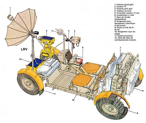
 This part deals with the lunar rover. It shows that the lunar rover of Apollo is full of incoherences. Link to the NASA document describing the lunar rover |
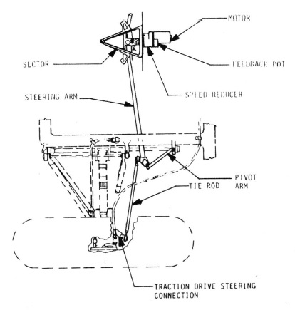
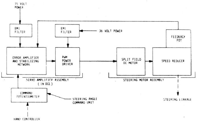 This is the diagram of the steering control block. It shows how the command of the hand controller can act on the speed of the rover. |
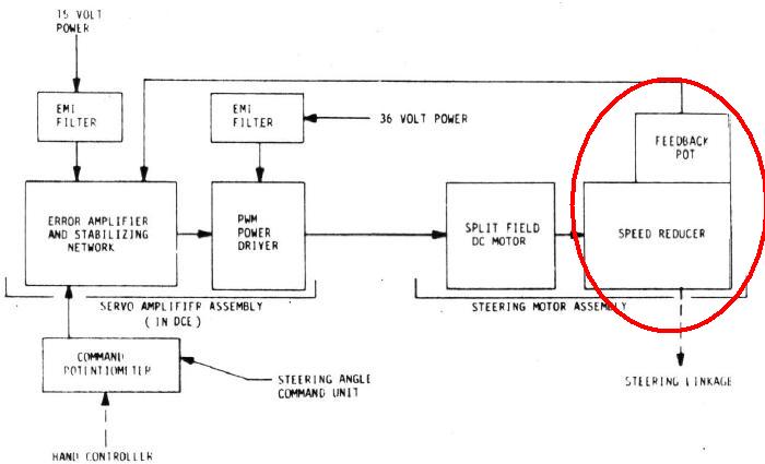 But there is a problem, because the feedback of the speed, which allows the command to determine as precisely as possible the desired speed, comes from the speed reducer; this has for consequence that the resulting speed will be consistently greater than the desired one. |
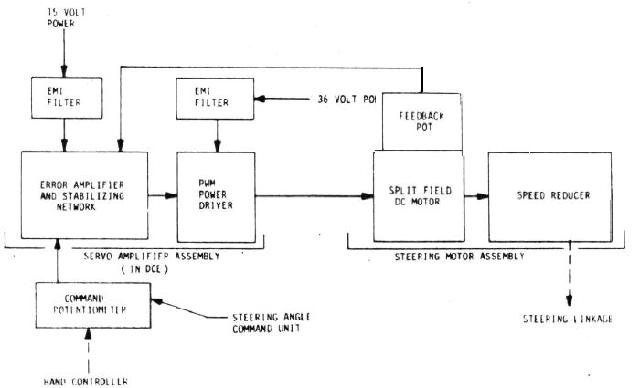 This is how it should have been connected: The feedback should come from the block preceding the speed reducer, so that the resulting speed effectively corresponds to the desired one. |
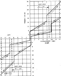 This graph represents the required torque to rotate the hand controller for the steering control; the left part of the graph corresponds with the wheels turned left, and the right part corresponds with the wheels turned right; the more the wheels are turned and the greater the effort the astronaut must give on the hand controller to turn the wheels. |
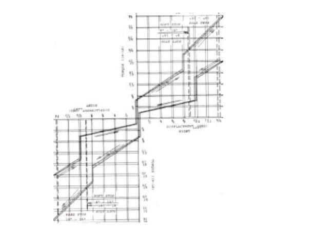 There is a symmetry between the wheels turned right and the wheels turned left, for, when I invert horizontally and vertically the graph and superpose it with the original graph, I obtain a quite good superposition. It is not surprising that the steering reacts the same whether the wheels are turned right or left. |
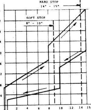 On this part of the graph of the wheels turned right, we can see that the effort on the hand controller regularly increases with the angle of the wheels, but there is a sudden discontinuity at a given moment; this discontinuity comes from a soft stop placed on the steering which makes that, when the steering has passed this stop, it becomes more difficult to turn the wheels; it is a protection against turning the wheels too brutally. But there is however something which seems illogical; the part of the graph corresponding with the astronaut pushing the hand controller right (which corresponds with turning the wheels right) suggests that the steering becomes harder a little before the soft stop, whereas the part of the graph corresponding with the astronaut pushing the hand controller back to the neutral point conversely suggests that it is a little after the soft point that the steering would become harder. |
 Either the steering becomes harder a little before the soft stop, and then the graph should look this way.... |
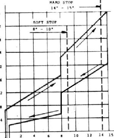
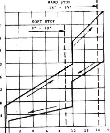 Or the steering becomes harder a little after the soft stop, and then the graph should look this way! |
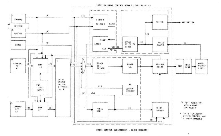 This is the diagram of the drive control electronics block. |
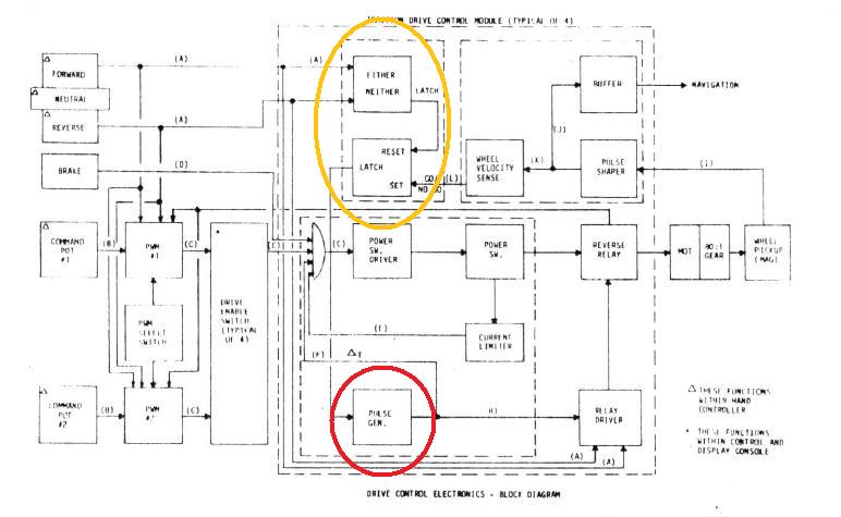 We can see that, when the astronaut moves the hand controller from forward to backward, there is a little waiting delay which is applied (by the block circled in red) before applying the command. But in fact this delay does not help: Suppose the rover is moving forward, and the astronaut suddenly moves the hand controller from forward to backward; even after the delay, the rover will still be moving forward, and the backward command will be applied as the rover is still moving forward; everybody knows that this kind of situation is very bad, that putting the gear on rear as a car is moving forward is catastrophic for the car and can kill its motor. Of course, you will tell me that the astronaut should be smart enough to know that he must not move the hand controller to backward as the rover is moving forward, and that he should first stop it; certainly, but he may do it unintentionally, for instance if the rover rides on a rock, and the astronaut is shaken and does not control his hand at this moment. So, there should be a protection against a such situation, which makes that an unintentional command of the astronaut generates no risk for the rover. |
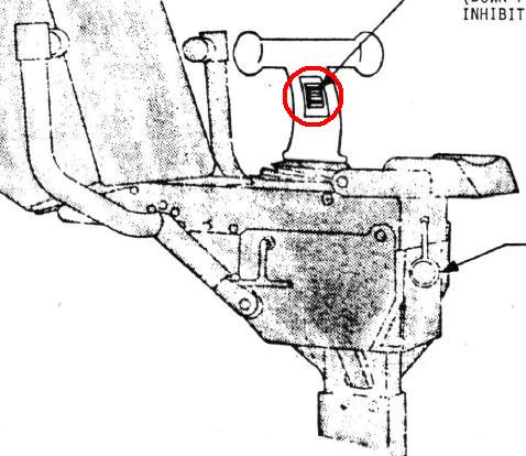 Sure, there was a reverse inhibit switch on the hand controller which was allowing to forbid from putting the controller on backward while the rover is moving forward; but see how this switch is inconvenient: It is practically not accessible to the astronaut with his pressurized gloves, he must have the greatest difficulty to change it; so he may decide not to use it; even if he manages to change it, he may also forget it to put it back to the lock position after having made a rear maneuver. Furthermore, while the astronaut is making a backward maneuver, he could also unintentionally put the hand controller on forward, and applying a forward maneuver as the rover is moving backward is also bad. From all this, it results that it is absolutely mandatory that the electronics should prevent from applying a backward command as the rover is moving forward, or vice versa from applying a forward command as the rover is moving backward. Is it possible? Yes it is possible and I am going to show you a schema which allows to prevent a backward command from being applied as the rover is moving forward, or conversely from applying a forward command as the rover is moving backward. |
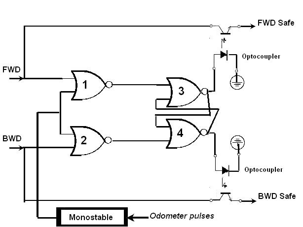 This interface would allow to bring the protection which is missing in the drive electronics control block. The odometer pulses which are generated when the wheels are turning go into a monostable circuit which allows to convert them into a permanent signal which is high when the wheels are turning, and low when the rover is stopped, or almost stopped. The output of the monostable goes into NOR circuits (circuit labeled 1 and 2) that the forward and backward commands also go into; when the rover is not moving, the output of the monostable is 0, and then allows the forward and backward commands on the outputs of the NOR gates 1 and 2; these outputs command a flip-flop constituted with the NOR gates 3 and 4; when the rover is stopped, the outputs of the gates 3 and 4 reflect the actual states of the forward and backward commands; but, when the rover is moving, the outputs of the gates 1 and 2 are forced to 0, whatever the state of the forward and backward commands, and this forces the flip-flop to the memorized mode: if the hand controller was on forward at stop, the output of the gate 3 is 1, and the output of the gate 4 is 0; if the hand controller is put on backward as the rover moves, as the flip-flop is forced to the memorized mode, the output of the gate 3 (corresponding to forward) will still be 1, and the output of the gate 4 (corresponding to backward) will still be 0; these outputs command optocouplers which let the signal through when they are activated, and block it when they are not; as the memorized forward output of the gate 3 is 1, it lets the forward signal through its optocoupler, and, as the memorized backward output of the gate 4 is 0, it blocks the backward signal through its optocoupler; even if the astronaut puts the hand controller on backward while the rover moves, the logic of the flip-flop will block the backward command which cannot be applied as long as the rover moves; it is only when the rovers stops, that the output of the monostable stops forcing the memorization of the forward and backward commands, and then the output of the gate 4 can take the state of the actual backward command, and unblock the optocoupler that the backward command is going through: Now the backward command can be applied and make the rover go backward. If works the same if the rover is going backward and the hand controlled is placed on forward. If necessary, redundancy could be added to this interface to make it still more sure. This interface would have allowed to fully secure the change from forward to backward, or vice versa, whatever the wrong commands that the astronaut could order. |
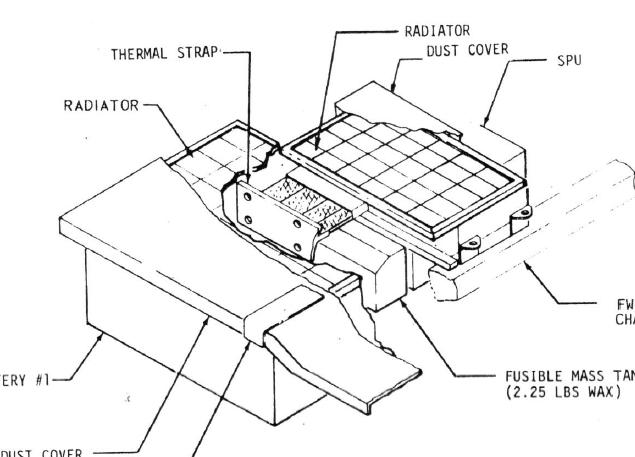 They put a dust cover over the batteries while the rover is moving in order to prevent the lunar dust from coming onto the surface of the batteries; they only remove the cover when the rover is parked near the LM to allow the recharge of the batteries. But it makes no sense: On the moon, unlike on the earth, the dust cannot billow, and there is thence no reason that dust would come on the batteries; on the other side, leaving the batteries exposed to the sun would allow the batteries to charge a little while the rover is moving and would thus allow to increase the range of the rover. |
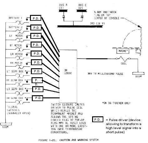
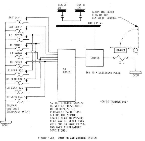 This is the caution and warning system of the rover. |
 When a default occurs, it goes through an OR gate and generates a pulse through a pulse driver which allows to magnetically release a spring which rotates a warning plate. Any default may release the warning plate. |
 This warning plate then appears on the top of the display console of the rover, and warns the astronaut that a default has occurred. The astronaut can put back the plate down in place for the next default even before the default has been cleared, for the pulse is generated only once when the default signal goes from low to high; it can't be generated as long as the default signal remains high; the default signal first has to go low before generating a new pulse when it goes high again. |
So, what are the problems with this caution and warning system? First you can see that some defaults are connected together; they should not be connected together; all the defaults should be individually connected to the OR gate. |
 This system also has a serious default. Suppose the first occurred default is persistent and does not disappear. It will go on forcing the output of the OR gate to a high level. Now comes a new default; as the output of the OR gate is already high due to the persistence of the original default, it will generate no change on the OR gate; and if the output of the OR gate does not change, it will generate no pulse on the pulse driver. The result is that the warning plate will not be released and the astronaut will not be warned that a new default has occurred. Can this system be improved? Yes, it absolutely can! |
 Now, if instead of connecting a pulse driver to the output of the OR gate, a pulse driver is individually connected to each default, and that the output of the OR gate is directly connected to the coil, it can allow to correct this problem. How? |
 If a first default occurs, it will generate a pulse through its pulse driver, and this pulse will go through the OR gate and will command the release of the spring; the warning plate rotates and warns the astronaut of the default. But, are you going to say, the previous system could already do it! |
 Now, it's where it becomes interesting. The original default has not disappeared and persists; but it has only generated a pulse on the output of its pulse driver which has allowed the first release of the warning plate. After the pulse, the output of the pulse driver has gone back to zero, and thus does not force the output of the OR gate to a high level. Now comes a new default; this new default generates a pulse on its own pulse driver; because the output of the pulse driver of the original default is currently zero, it does not prevent the pulse of this new default from going through the OR gate and activating the coil; the warning plate can be released again and warn the astronaut of the occurrence of a new default. So, unlike in the previous system, this modified system does not prevent the astronaut from being warned of a new default when a previous default persists. It is definitively better and it is this way it should have been designed. |
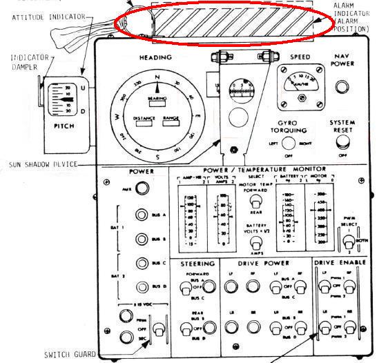
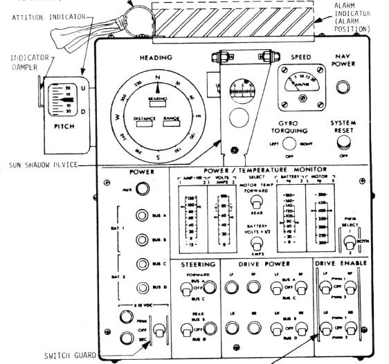 The control display console allows the astronaut to monitor all the events of the rover. |
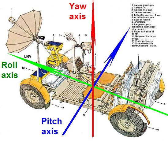
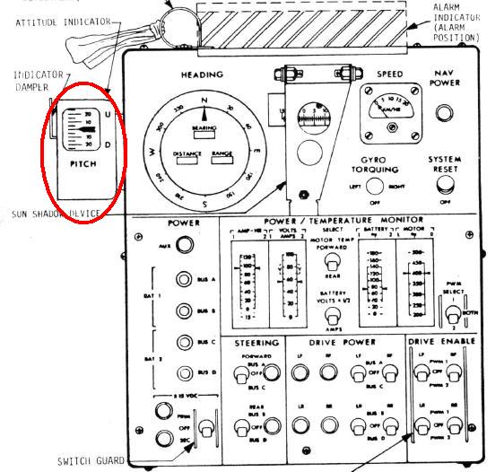 On the left side of the console, there is an angle indicator which allows to inform the astronaut of the rover's angles around the horizontal axes. |
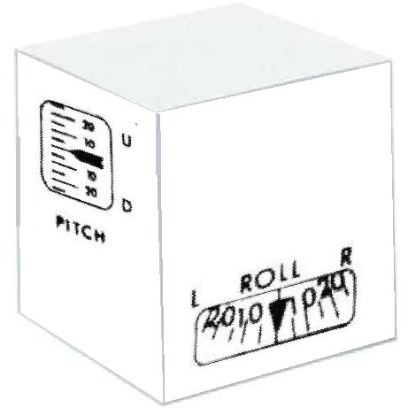 This indicator is a box which contains two angle measuring systems which are placed perpendicularly to each other. |
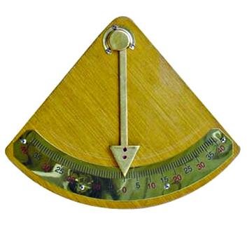 These angle measuring systems use the principle of the pendulum to work; they use the lunar gravity in order to know the exact vertical. They are of course more sophisticated than what I show here which is only intended to explain the principle of the measure. These systems measure the rotation angle around the axis which is perpendicular to their plane, and that is why they are placed perpendicularly to each other. The roll angle is the angle of rotation around the lengthwise axis of the rover, and the pitch angle is the angle of rotation around the horizontal axis which is perpendicular to this axis. |
 Normally, the indicator is oriented so that the astronaut can read the roll angle in front of him; if he looks on the left side, he could read the pitch angle, but it is not very convenient for him to read it that way, not to say impossible. |
 That's why the astronaut has the possibility to manually turn this indicator of a quarter of turn counter-clockwise, so that he can read the pitch angle instead. But this is ridiculous, if he turns the indicator of a quarter of a turn, the two measuring systems are also going to be turned of a quarter of a turn, which means that the one which is supposed to measure the roll angle will in fact measure the pitch angle, and vice versa. Although the angle reading that the astronaut has in front of him is now labeled "Pitch", it is still a roll angle that the astronaut will read. Turning the angle indicator does not help; if the astronaut really wants to know the pitch angle, the only solution would be for him to try to read it on the left side of the indicator as it is in normal position...which is practically impossible for him. The documentation says that the pitch and roll angles are sent to the navigation system to update the navigation; but, if the astronaut turns the indicator, not only it will not allow him to read the pitch angle, but furthermore the navigation will misinterpret the angles and will use the pitch angle instead of the roll angle, and vice versa, since the rotation of the indicator is purely manual, and the navigation system is not informed of this rotation, and thence does not know the angles are swapped! |
 Anyway the roll and pitch angles are not necessary useful to the navigation system if the gyroscope is horizontally stabilized. So, normally, the gyroscope should give the variation of angle around the true vertical and not the vertical to the rover, which means that the pitch and roll angles are not necessary to update the navigation. The only interest of the roll and pitch angles might eventually be to study how the lunar terrain is accidented, but it is a very limited interest, since they are going to continually change with the terrain, even if the rover goes straight. |
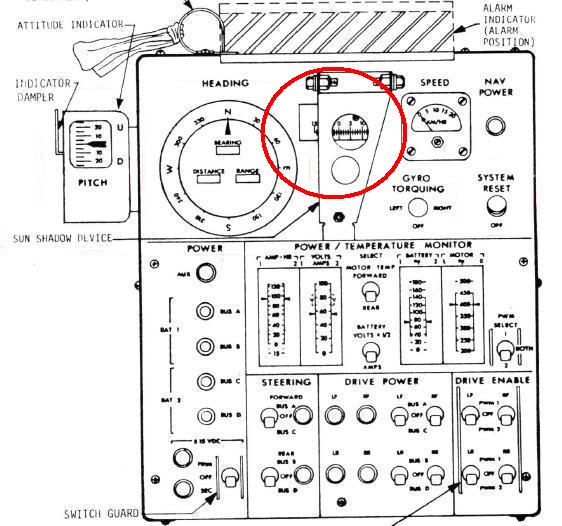 On the display console there is also a special device (I have circled) which is called "sun shadow device". |
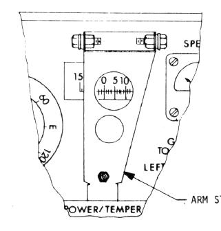 This instrument allows to measure the position of the sun shadow on a graduated scale, provided that the sun is almost in the back of the rover, and would allow to update the navigation system. But the orientation of the rover relatively to the sun allows in no way to know the orientation of the rover relatively to the LM and is completely unrelated with it. I am going to illustrate it on two examples. |
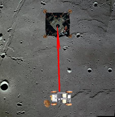
 On this first example, the rover turns around the lunar module; the direction of the LM is constantly perpendicular to the axis of the rover all along the turn; so the orientation of the rover relatively to the LM does not change all along the turn; yet, the orientation of the rover relatively to the sun does constantly change all along the turn. |
 On this second example, the rover is going straight, so its orientation does not change relatively to the sun. But its orientation relatively to the LM keeps changing. |
This is why the measure of the sun's shadow helps in no way to update the orientation of the rover relatively to the LM, and is of no use for the navigation. |
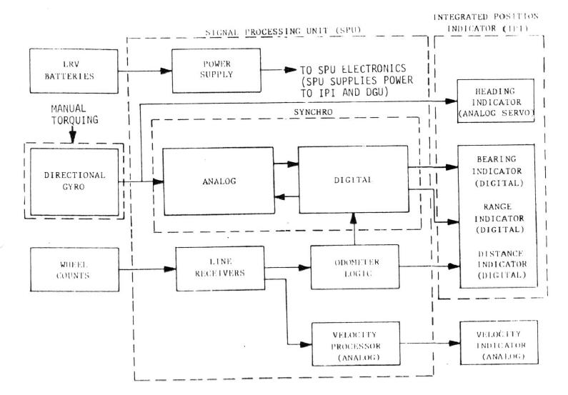
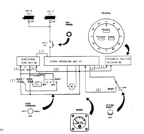
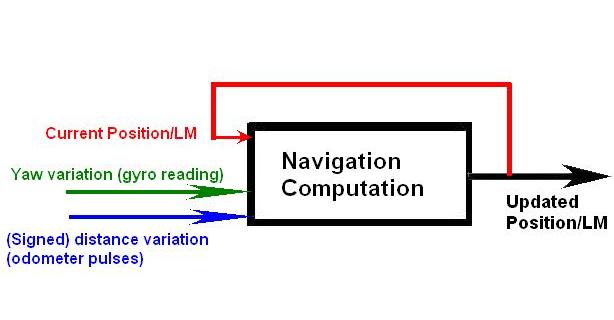 The navigation system works this way: Knowing the current position of the rover relatively to the LM, that is the orientation of the LM relatively to the rover, and the distance of the rover to the LM, the navigation constantly updates this position by using the reading of the gyro which informs on the variation of angle around the vertical axis, and the variation of distance given by counting the odometer pulses, to compute a new updated position of the LM. When the wheels turn, they generate what is called odometer pulses; each wheel generates a certain number of odometer pulses per revolution; in order to know the distance that a wheel has ridden, the odometers pulses which have been produced during this distance are counted, and then this count is multiplied by the circumference of the wheel and divided but the number of odometer pulses per revolution of the wheel; measuring the speed is done by counting odometer pulses on a given period: The more there are odometer pulses in this given period, and the faster the rover goes. |
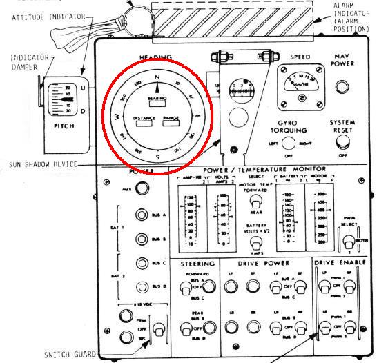 The heading indicator allows to know the position of the rover relatively to the LM. |
The navigation system allows to update the position of the LM and thence to update the indication of the heading. But the navigation system must not only to know the variation of distance of the rover, but also the direction of this variation (i.e. the variation of distance must be signed). |
 Let's start from this position of the rover relatively to the LM. |
 You can see that, if the rover moves straight the same distance forward or backward, the new orientation of the rover relatively to the LM will not be the same; this is why the navigation needs to know, not only the distance the rover has ridden, but also in which direction. |
 Yet they say this in the documentation: "The odometer logic cannot distinguish between forward and reverse wheel rotation; therefore, reverse operation of the LRV adds to the odometer reading". That means that the variation of distance is absolute and not signed. |
 The first consequence of this is that, if the rover keeps going forward and backward, it may make believe that the rover is far from the LM when it is in fact close to it, since the distance is counted the same when the rover goes backward as when it is going forward. |
But, there is a still more annoying consequence which is that it will falsify the update of the rover's orientation relatively to the LM. And having a wrong orientation of the LM relatively to the rover is more problematic than having a wrong distance of the LM to the rover |
 Indeed, if the astronaut thinks that the LM is closer than it really is, but still goes in the good direction, after he has come to the point he thought the LM was, may be he won't find the LM, but he will still have come back closer to the LM, and, if he goes on in this direction, he will finally find it; eventually, after having reached the point he thought he would find the LM, he might have the latter in view. |
 On the other hand, if the astronaut has to come back on foot and starts in the wrong direction, not only he will not find the LM when he will reach the point he thought the LM was, but moreover he will have got farther from the LM, and if he persists in this wrong direction, that he thinks to be the good one, he will get farther and farther from the LM and will never find it; it will then end tragically for him! |
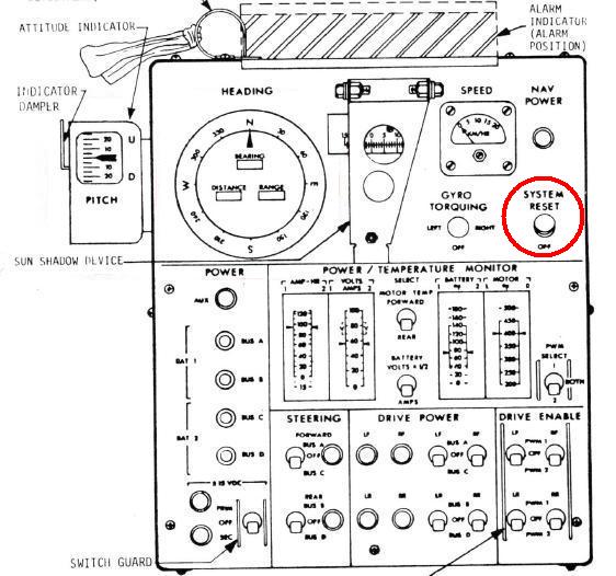 The astronauts had a reset button to initialize the navigation system at the start of the mission. This button was setting all parameters to zero. The problem is that they could change this switch at any moment of the mission, there was no protection against using it in the middle of the mission; yet, if they use this button in the middle of the mission, the navigation will lose its current data, and will become unable to make a correct update from that moment, for the navigation updates a new position from a previous one. |
It was not impossible that the navigation station could have a power loss during the EVA. In a such case, the display console was keeping displaying the last information it had at the moment of the power loss. If the power loss was permanent, the navigation system was becoming totally inoperational of course, but, even if it only was temporary, and the rover had moved during the power loss, when the power was restored, the navigation station was using not the current position of the rover, but the one it had at the moment of the power loss, which was not the same of course if the rover had moved. In that case, the navigation system had to be reinitialized (and it also should in case the astronauts would inadvertently use the reset button). In the documentation, they say that the rover had to ride 50 meters after the start of the reinitialization before the data of the navigation station were valid again. So, imagine that the rover has a problem which makes that it cannot move any more at that precise moment? If the astronauts have to come back on foot to the LM, they have to know in which direction the LM is, otherwise they might be incapable to go back to it. But the rover had to ride 50 meters before the navigation station gives a valid indication, and it can't. |
 So, what are the astronauts going to do? Carry the rover on 50 meters till the navigation station gives valid data? |
 But the wheels of the rover probably need to have a contact with the ground, so the astronauts are going to push it on 50 meters instead! |
Let's be serious; if the navigation system has lost a valid reference, there is no way that it can acquire it again all by itself; after having ridden 50 meters, the navigation will have updated from an invalid reference, and will still have an unvalid reference. |
 The only way to reinitialize the navigation system would be to give it a valid reference. The only solution would be to emit a signal on an antenna, and orient this antenna till to get the best signal in return from the LM; the distance of the LM could be acquired by measuring the delay between the emitted signal and the received signal. |
 But, and that's the whole problem, the navigation system is incapable of orienting the antennas itself. Both are oriented manually by the astronauts. They have provided for a commanded rotation of the camera, but they have provided nothing for the automatic orientation of the antennas. Yet, allowing the antennas to be remotely oriented would have allowed not only to automatically orient them so to always have the best reception, but also would have allowed to make a reinitialization of the navigation system, and this is essential for the safety of the astronauts, for, if they don't know where the LM is, and are incapable to go back to it, it might mean death for them. But sending images to the earth is more important than their safety, isn't it? so, reinitializing the navigation station would need the cooperation of the astronauts; and, even if it could work this way, once the best orientation is found, the navigation station would still need to get the current orientation of the antenna, which it can't either; so, is the astronaut going to use his sextant to find this orientation and give his measure to the navigation station? Let's be serious, once that the navigation station has lost its reference, there was no way that it could acquire it again, because nothing has been provided for it. |
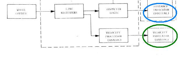 This is the part of the navigation subssytem which concerns the management of the wheels. It allows to update the distance and speed indicators. |
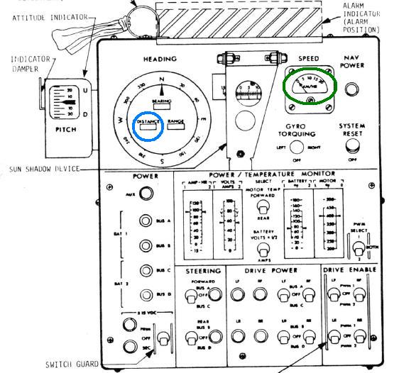 I have circled in blue the distance indicator, and in green the speed indicator on the display console. |
 I have explained that the measure of the speed is done by counting odometer pulses on a given period. So the velocity block should logically be related to the odometer logic bloc. Instead of this, it is related to the previous block which gives no information relative to the odometer pulses. |
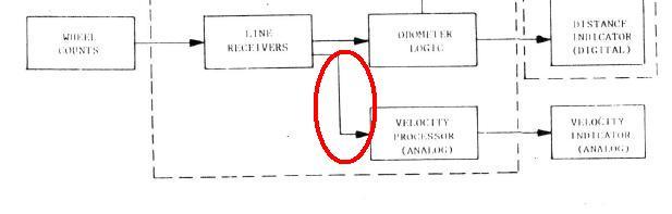
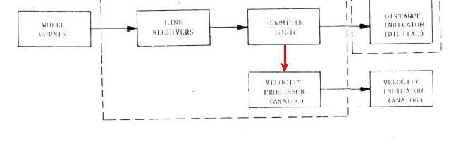 This is the way the velocity block should have been connected, that is to the odometer logic block, in order to get the odometer pulses which allow it to measure the speed. |
 They say that the navigation station updates separate counts in north and east accumulators. But it cannot work this way: The navigation updates an orientation relatively to the LM; after it can eventually use this updated orientation to update a north and east indications. |
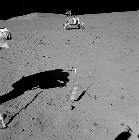
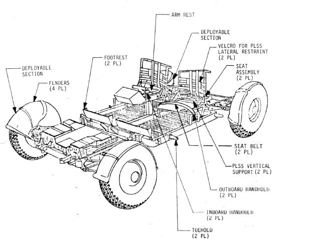 About the crew components, they say this: "the seat bottom contains a cutout to allow access to the PLSS control valves and includes provisions for vertical support of the PLSS". |
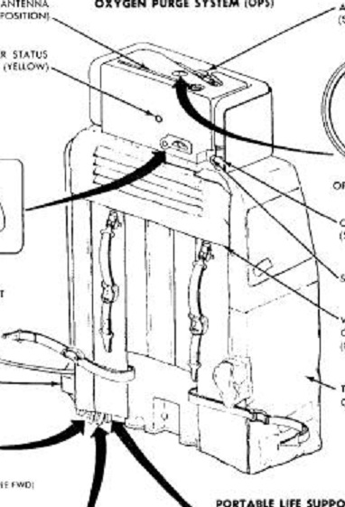 These manual valves, which are provided in case of the failure the automatic regulation valves, are located at the left bottom of the backpack, at the place indicated by the arrows. |
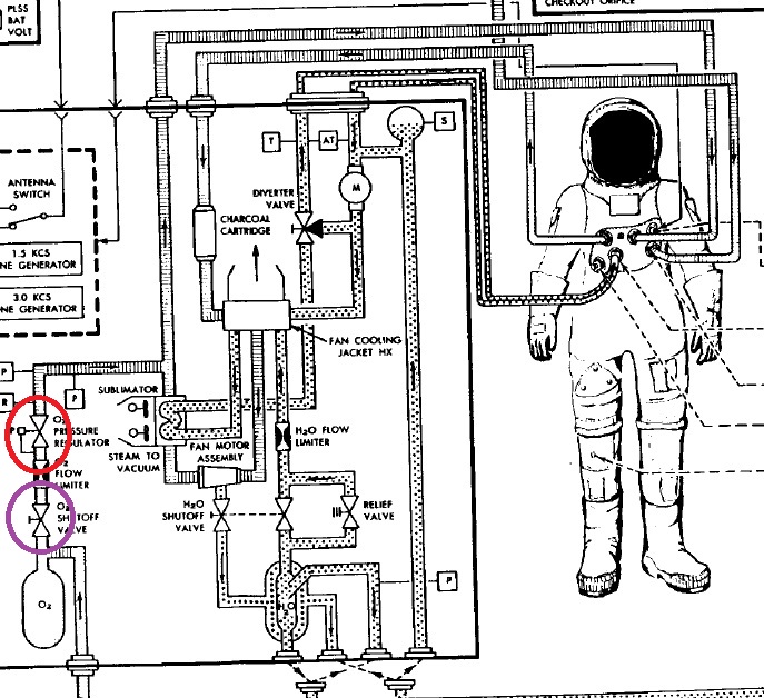 For instance there is an automatic regulation valve which opens when the oxygen pressure goes under a value, and closes when it goes over another value. But it is possible that the automatic regulation valve has a failure and does not close when it should; as a consequence it may generate an overpressure that the astronaut can read on his arm gauge. The solution to solve this case is for the astronaut to shut the manual valve in order to block the entry of oxygen and stop the overpressure before it causes a fatal problem. |
This valve is one of the valves located under the backpack. |
 The astronaut has a pressure relief valve located on his arm... |
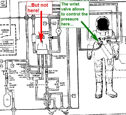 But this valve allows to control the oxygen pressure in his suit, and not in the PLSS itself. In case of a persistent overpressure, the astronaut must still close the valve under his backpack... |
 ...otherwise, the astronaut will feel fine as long as the backpack can hold the pressure thanks to the relief valve on his wrist, but, when the overpressure makes the tubes explode in the PLSS, he will feel much less fine! |
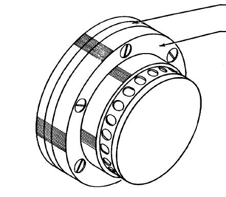
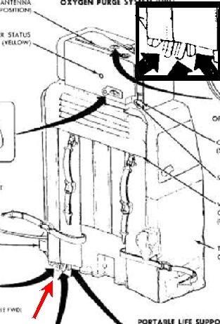 Now, look at the valves under the backpack; they are small and close to each other. When the astronaut must shut a valve, as they are behind him, he can't see them; with his naked fingers, he could feel them, and shut the good one, but, with his pressurized gloves, and the impossibility of seeing them, there is no way that he can safely identify them, and shut the good one; he might shut the wrong one, or shut several ones in the same time. |
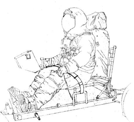 If a cop was seeing you strapped like this in your car, you might be sure that he would give you a ticket for being unsafely strapped. This seat belt certainly does not guarantee the safety of the astronaut. |
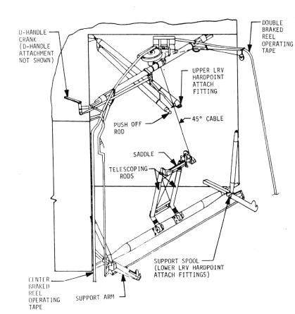 This figure shows the system which was allowing to deploy the rover. We might wonder how the rover could hold in its compartment. |
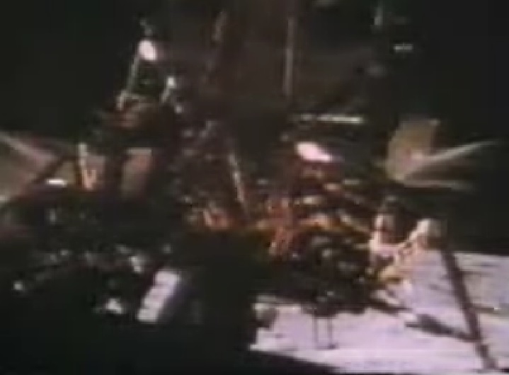
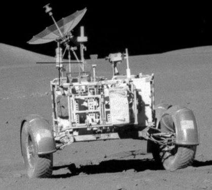
 This (sped up) demonstration of the NASA is supposed to prove that the rover could be stowed in its compartment and could be easily deployed. |
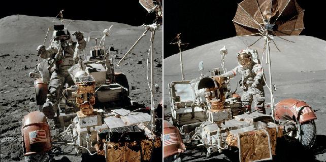
 However, you can see that: 1) when the rover is stowed, almost all the available space is taken by the wheels of the rover. 2) when the rover is deployed, you can see that it is only with its naked chassis; there is no equipment at all on the rover, not even the fenders of the wheels. |
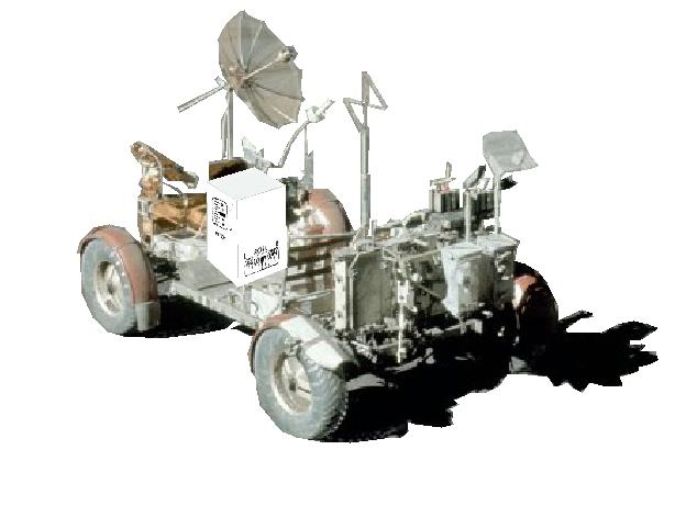
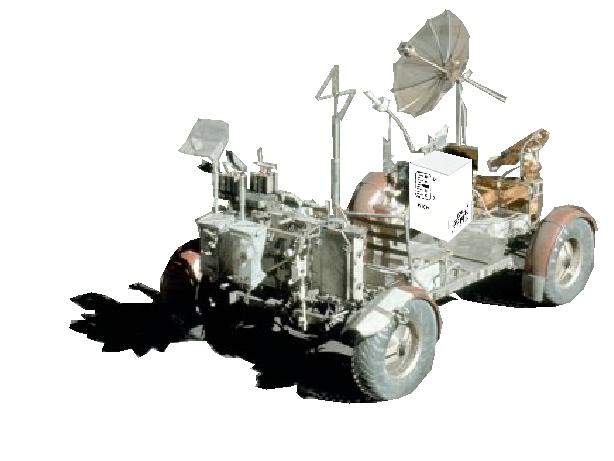
 There is clearly a constrast between the naked rover which is deployed in the demonstration (left of the stereoscopic view), and the fully equipped rover (right of the stereoscopic view). |
 It is absolutely obvious that, if the rover had had its full equipment, it would not have held in its compartment, there is not enough room in it for the full equipment of the rover. |
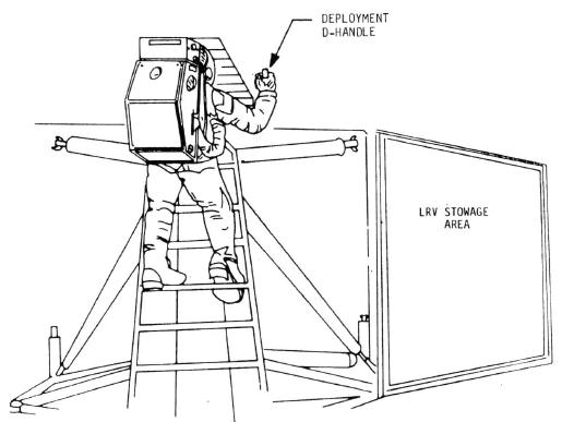 Another thing which does not seem normal is the position of the deployment handle. The astronaut had to climb on the LM to reach the deployment handle. So the engineers were not able to devise a deployment handle placed lower, which was not forcing the astronaut to play the acrobat to reach it? |
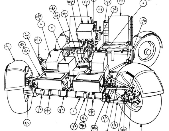
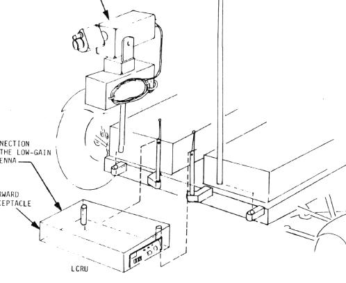 This figure shows how the TV camera was installed. |
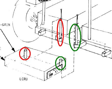 Two support posts of the LCRU, respectively circled in red and green go into two inboard receptacles, also circled in red and green. |
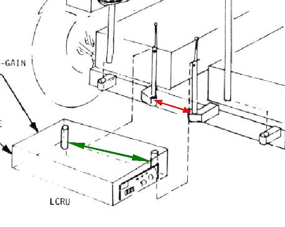 But, what's strange is that the distance between the two support posts is consistently greater than the distance between the two inboard receptacles that they must yet go into. Are the distances elastic on the rover? |
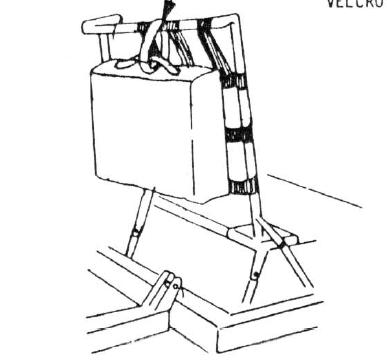 On this schema, they explain how to suspend a bag behind a seat with Velcro. |
But, with all the stuff which is behind the seats, we can wonder how the bag could hold behind the seat. |
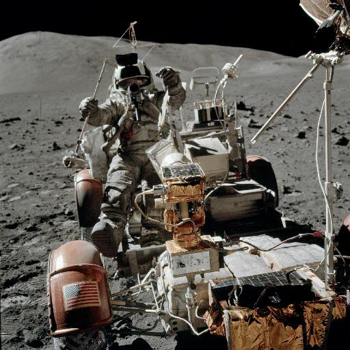 Now, to close this part, some strange photos of the rover. On this photo of Apollo 17, referenced AS17-134-20453, there is something strange, if we make a close-up of the battery... |
 Someone has told me that the battery was not broken, but shaded instead. But that does not explain the elements I have contoured! |
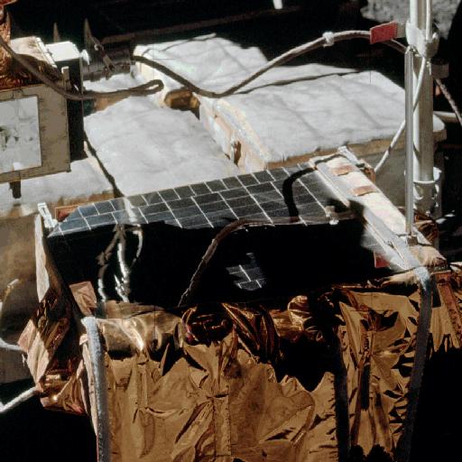 Seriously, how is it that the battery can appear so seriously damaged? |
 And, if we compare the support of the TV camera on the photos AS17-134-20453 and AS17-134-20477... |
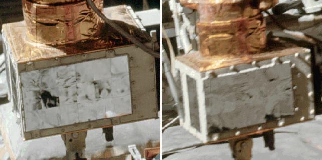 ...Why do the screws of the support appear much whiter on the second photo than on the first one? You might say that it is because this side is more lit on the second photo than on the first one, but you can see that is is not the case: the majority of this side is duller on the second photo than on the first one. The explanation of the side being more sunlit to explain the white screws could eventually fit for the upper edge, but not for the lower edge! |
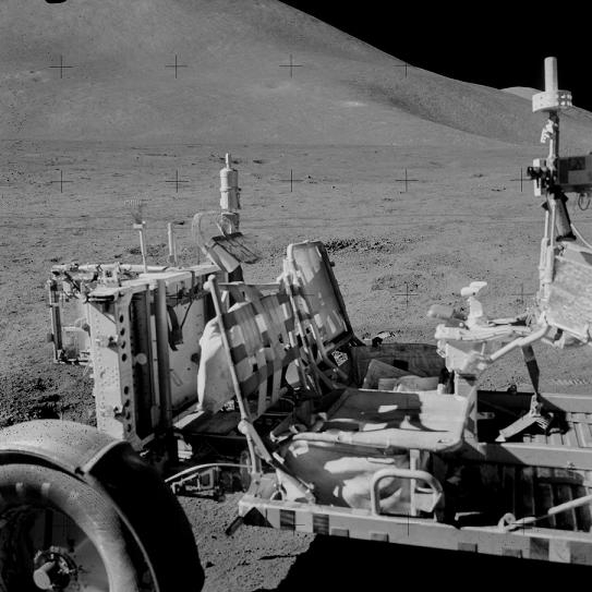 And, on this photo of Apollo 15, referenced AS15-92-12434... |
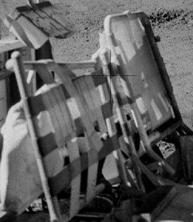 ...Why does the top of the passenger seat appear abnormal? |
 To conclude this part, in this sequence of the rover supposedly riding on the lunar ground, the camera is first filming in the direction of the progression of the rover, and the lunar ground comes frontally, which is normal... |
 But then the camera turns on the right; as the camera is no more filming in the direction of the progression of the rover, the lunar ground should no more come frontally, it should shift on the right...And yet it keeps coming frontally! |
 After the rover had been deployed from the lunar module, all its parts had to be installed on it, and it was not an easy task for the astronauts, with their pressurized gloves, and the poor vision they had with their visors. |
 On the video, we don't see them do this work, they are off field, hidden by the lunar module, we only hear them. |
 I doubt they would have been able to do all this complicated work on the moon, they certainly got "magical" help. |
 In particular, they had to install the steering system of the lunar rover. |
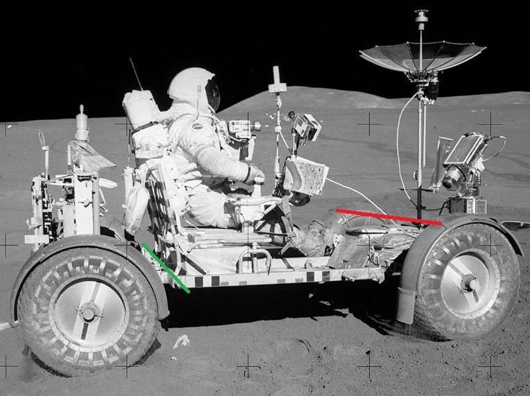
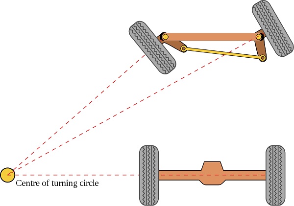 This steering system was using the ackerman geometry which allows wheels to turn differently from each other, so to optimize turns. |
 There was both front and rear steering, but only the rear steering would have worked at the start. The front steering would have initially refused to work. There was a switch which was allowing to choose between battery A and C; they cycled several times this switch, but to no effect at installation. There also was a fuse, but we are sure that it didn't melt, for they later managed to make the front steering work without changing it. We can wonder why cycling the battery selection switch would not have repetitively worked at installation, while it would finally have accepted to work later, at the beginning of the second EVA. |
The consequence that the front steering was not working during first EVA is that the front wheels could not turn during this first EVA. And I was sure that the clue was to find a photo of first EVA on which we could find evidence that the front wheels were turned. |
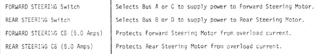
 And I found it on photo AS15-85-11471, a famous photo on which we can see Scott (or what is supposed to be Scott) seated on the rover. |
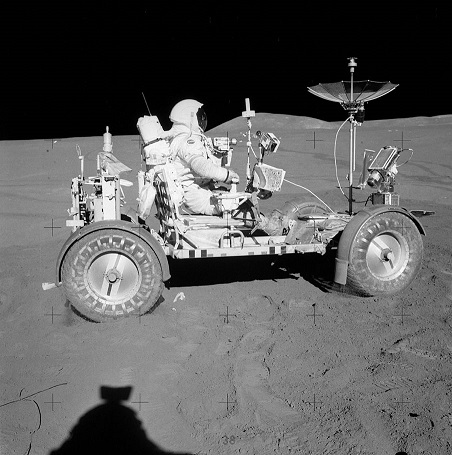
 If we attentively examine the wheels, we can see that, while we can't see the central band on the rear wheel, we can see it on the rear of the front wheel, which shows that it is turned left. |
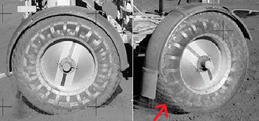
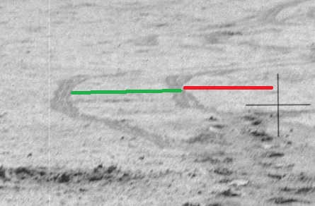
 And, to counter the argument that it could be the rear wheel which is fact turned, I give another indication that the front wheels are effectively turned. If I draw a (red) line between the two same folds of the fenders of the front wheels, and I compare it with a (green) line following the back side of the chassis, just behind the seats, we can see that the red line is consistently turned left relatively to the green line, which confirms that the front wheels are effectively turned left. |
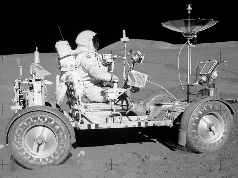 So, while the front wheels could not be turned in first EVA, because of the front steering not working, there is evidence that the front wheels can be seen turned in this EVA. Now you understand why the front steering had not to work in the first EVA: It was allowing to give a hint of the fakery. |
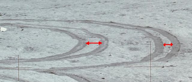
 And it is not the only surprise. In the mission report of Apollo 15, they say that the simultaneous use of the front and rear steerings was allowing to make a turn with a minimum radius of 122 inches, which makes 3.1 meters. It means that we should not see on the photos of Apollo 15 a turn with a radius which is under 3 meters... |
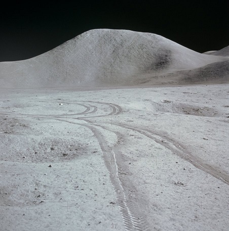
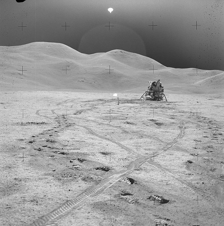 ...and yet, on the photo AS15-82-11056... |
 |
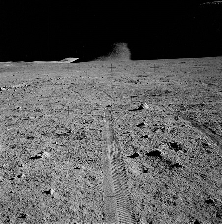
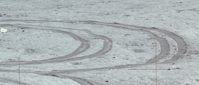
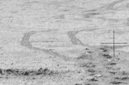 We can see a very suspicious turn. Is it possible to prove that it does not have the minimum required radius? |
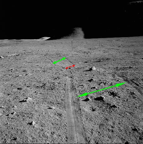
 We can see that the radius of this turn is equivalent to the gap between the tracks (and even slightly smaller). |
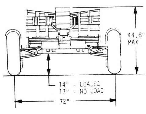 And, in the documentation of the lunar rover, it is said that the gap between the wheels of the rover was 72 inches, so 1.83 meter. |
It means that the radius of this turn, far from being over the minimum radius which could be obtained with both steering systems, was almost half of it! |
 And the show goes on with the photo AS15-85-11403. |
 We can see that the gap between the rover tracks I have indicated in red is much smaller than the gap which precedes. And to show that it does not just come from the effect of distance which makes that the gap progressively decreases, the gap increases again beyond. |
 Another surprise on the photo AS15-87-11835. |
  We see two sets of pairs of tracks close to each other. |
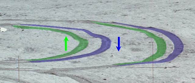 One pair of tracks, I have colored in green, goes in one direction, and another pair of tracks I have colored in blue, goes in the converse direction (the directions may be inverted). |
 Normally, the gap between the wheels has not changed between the two directions, so the gap between the corresponding tracks should be the same, and we can see that it is not. |
 A last surprise on the photo AS15-82-11108; we can see the rover in the distance. |
  The rover might seem normal when seen from far, but, when we see it closer, we can see strange details. |
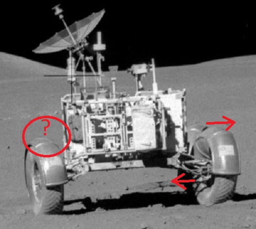 We can notice that the rear wheels are turned left, but the right front wheel is seen turned right; we don't see much of it, but enough to be sure that it is turned right. And, concerning the left front wheel, we cannot see it at all, it appears to be absent. So this marvelous piece of technology can ride with three wheels only, and moreover with wheels turning in opposite directions. |
 A last surprise, in a video this time. In Geology station 1, at time 122:25:01, we find the following comment: "As Jim climbs on the rover, the image starts to jiggle". Here is an excerpt of the corresponding video. We can effectively see the image consistently jiggling, because Jim makes the rover sway as he climbs in it. |
 But, if the rover sways, so does the high gain antenna, which thus does not remain correctly oriented toward the earth, which means that there should momentarily be a loss of the transmission of the video to the earth. |
And yet we see no break of transmission on the video, for the image disappears at no moment. |
 Apart from these some trivial things, everything is fine, so why do I try to split hairs? |
