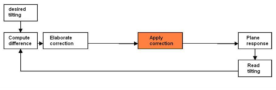
Redundant information in Apollo 8

 In Apollo 8, the instrumentation system, of which they show the schema here, had the task of recording various informations; but were these informations really useful? |
 We first see that there are three different timing informations. In fact only one is really necessary... |
 ...And the two other ones are redundant and can be suppressed. |
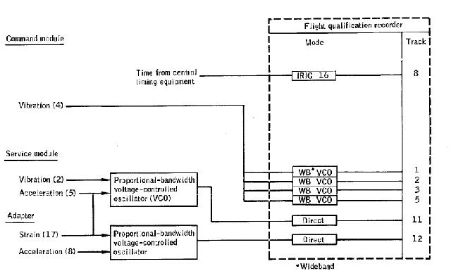 That makes as much useless information which does not need to be recorded. |
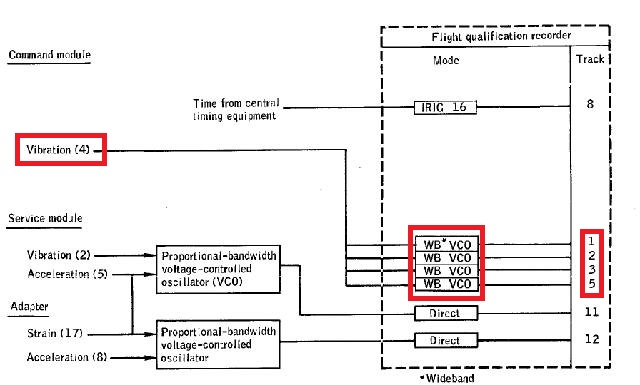 Then we can see that the vibration is recorded four times, modulating four different VCO; even if the VCO are tuned on different frequencies, they convey the same information, and so they are redundant. Only one needs to be recorded. |
 So, we only keep one recording of the vibration, and remove the other ones. |
 Then we see a block on which we see that the vibration is input, while it is already recorded above, and the acceleration is input, while it is also input on the block below. And, if you think that it would not be the same acceleration, of course it is the same acceleration, for all the points of the command module move the same, and so have the same acceleration. The same for the vibration. |
 So this block contains redundant information, and can therefore be suppressed. |
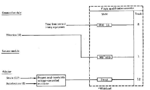 After having suppressed the redundant information which does not need to be recorded, we then obtain the final schema of the instrumentation system, in which only the really useful information is recorded. |
 Redundant information does not give more information than the really useful information. |
 After having heard an opera of Mozart, the Emperor of Austria said to Mozart that his opera was containing "too many notes". To what Mozart replied that his opera was containing just as many notes as required. |
But, here, the instrumentation system does not record as many informations as required; most of the informations it records are really redundant. |
 In the mission report of Apollo 8, they show this for the schema of the interphone which was allowing the rescue swimmers to dialog with the crew of the command module. But this schema makes no sense, for the output of the speaker, instead of being an output of an amplifier, is another input of the amplifier which allows to amplify the voice of the swimmers; and, when the push-to-talk button is pressed, the speaker and the microphone are both connected to the wire connection communicating with the crew of the command module, through the amplifier. In fact, with this schema, the swimmers could talk to the crew of the command module directly through the speaker, without pushing the push-to-talk button, but they could not hear the crew. |
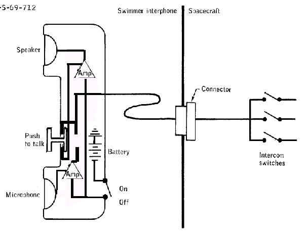 In fact, this is how this interphone should have been connected. |
 When the push-to-talk button is not pressed, the input of the amplifier, that the speaker is an output of, is connected to the wire connection allowing the communication with the crew; the swimmers can hear the crew of the command module. |
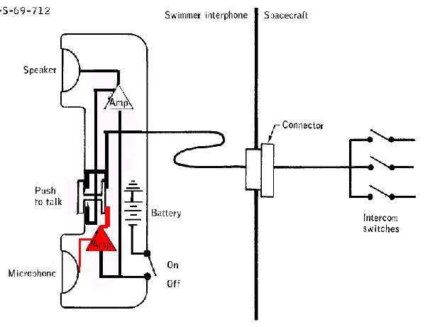 And, when the push-to-talk button is pressed, the output of the amplifier, that the microphone is an input of, is connected to the wire connection allowing the communication with the crew; the swimmers can talk to the crew of the command module. |
 Any electronician, who has a minimum of competence, would immediately see that the schema they show for the interphone makes no sense, and would know how it should be made. |

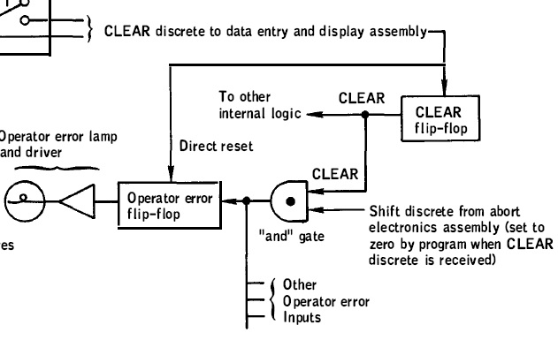 In the mission report of Apollo 9, they say that, when the clear pushbutton is pressed, it turns off the operator error light, but, if the shift discrete signal is still high when the clear pushbutton is released, the operator error light would go on again, according to what they say. |
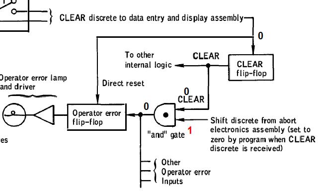 The clear signal and the shift discrete signal are inputs to an AND gate, of which the output allows to light the operator error light when it is set to 1. The AND gate outputs a 1 if its both inputs are 1, and 0 otherwise. When the clear pushbutton is pressed, as the AND gate has one of its inputs set to 0, it outputs a 0, and therefore the operator error light goes off. |
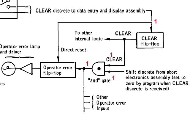 When the clear input is 1 again, if the shift discrete signal is 1, the AND gate outputs a 1, because its both inputs are 1, and the operator error light goes on; this is what they are implying in their explanation. |
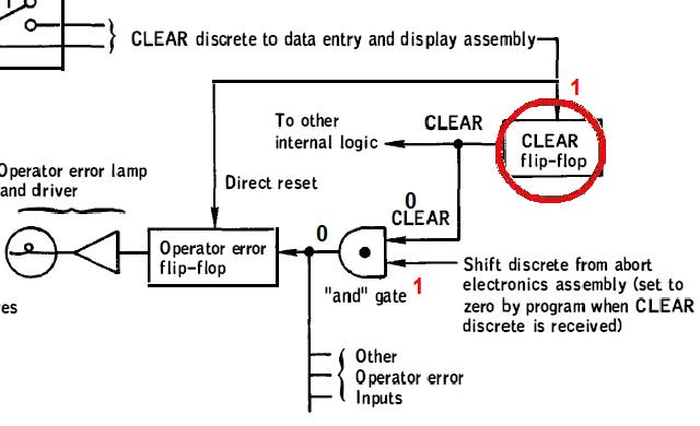 But in fact it is not directly the clear signal which is an input to the AND gate, but the output of a flip-flop (circled with red) which is set to 0 when the clear signal is set to 0, and remains set to 0 after the clear signal becomes 1 again; the output of the flip-flop only becomes 1 again when the shift discrete is set to 0, but currently the latter is set to 1. That means that the AND gate, which has the output of the flip-flop as one of its inputs, outputs a 0 since the flip-flop currently outputs a 0, which means that the operator error light does not go on, unlike what they said. |
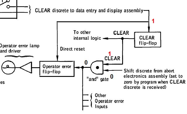 When the shift discrete signal is set to 0, the flip-flop is resetted, and outputs a 1 again; but, as the shift discrete is currently 0, and is an input to the AND gate, the AND gate still outputs a 0, and the operator error light remains off. It means that the operator error light does not goes on if the shift discrete signal is 1 at the moment that the clear pushbutton is pressed; even if it goes low a moment later after the clear pushbutton has been pressed, the operator error light will not go on. |

 In Apollo 10, after the LGC had stopped commanding the gimbal system of the engine, this one was continuing to move for some time, by inertia. If this time was remaining limited, it was not detrimental to the command of the engine. In Apollo 10, a test was made 0.25 second after the gimbal system had stopped being commanded to see if it was still moving (in pitch and roll). If it was detected as still moving, an alarm was displayed. Although, as it did not prevent the phasing maneuver from being successfully made, the engineers concluded that the delay to test if the gimbal system had stopped moving could be increased a little, and it was set to 0.5 seconds for Apollo 11, so that the alarm would not be displayed in Apollo 11 in a such situation. |
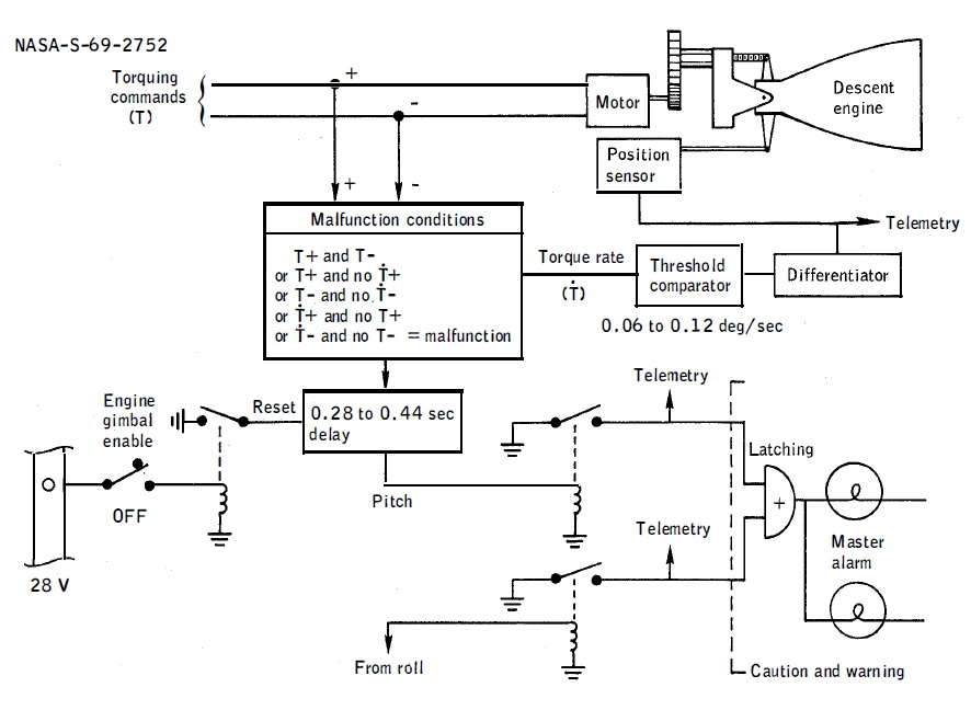 They show this for the schema of the Descent engine trim control. |
 When a command is being sent to the gimbal system, the switch which is circled is closed, which energizes an electromechanichal relay, which closes a switch which allows to maintain the counter in reset position; the timer does not count. |
 When the command is stopped being sent to the gimbal system, the circled switch is opened, stops energizing the electromechanical relay, the switch which was maintaining the timer in reset position is opened, and the timer starts counting. |
 As long as the timer is counting, if the torque rate indicates that the gimbal system is still pitching, though it receives no more a pitch command, the timer does not output it. |
 When the timer has reached its programmed count, it stops counting, and then the torque rate should indicate that the gimbal system is no more pitching, which is the normal situation. |
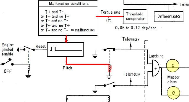 But, if, when the timer has reached its programmed count, and stopped counting, the torque rate indicates that the gimbal system is still pitching, which is an abnormal situation, the timer outputs a signal which energizes an electromechanical relay, which closes a switch, which allows to illuminate the alarm indicators. The astronauts are warned that the gimbal system has taken too much time to stop moving after it has been stopped being commanded. It works in a similar way for the roll. |
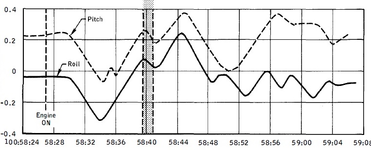 In Apollo 10, the greyed area shows that, after a delay of 0.25 seconds, the gimbal system has been detected as still moving instead of being at rest. The alarm indicators have been illuminated. |
 But, while, if the delay had been increased of 0.25 seconds no alarm should have been displayed, if I shift the tested area of 0.25 second on the graph (area colored in red), we can see that, in this area, the gimbal system is still pitching and rolling (this is especially visible on the pitch, less on the roll), which means that, even if the delay had been adjusted as they plan to do it for Apollo 11, the warning indicators would still have been illuminated. |
 This looks like an inappropriate decision of the engineers! |

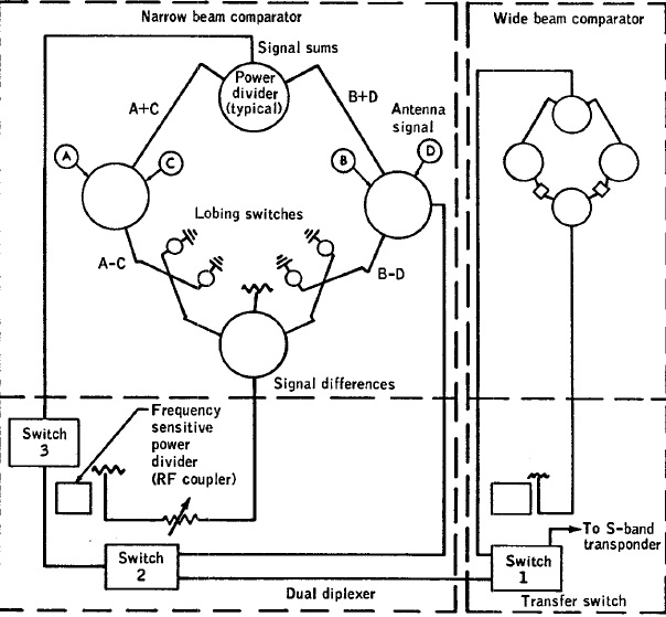
 In Apollo 11, when the steerable antenna was selected after acquisition on revolution 4, difficulty was encountered in maintaining communications. It would be because the initial schema of antenna coverage was not including the thruster plume deflectors, which were added to the lunar module at the launch site! This shows the level of unprofessionalism of the project (but we are accustomed to it). The schema of the S-Band steerable antenna coverage restriction would imply that there is a whole set of combinations of pitch and yaw angles which allow the communication. |

In fact there is only one combination of the pitch and yaw angles which allows the communication with the earth, the one which orients the antenna toward the earth. |
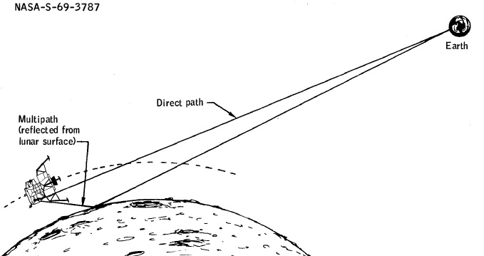 (In the mission report of Apollo 11) They also talk about a problem of multipath reception which would decrease the quality of reception. The signal from the earth and the reflected signal coming from the moon would hinder each other and would cause tracking losses. |
 But it is completely ridiculous, for, when the antenna is oriented toward the earth, it only receives the signal directly coming from the earth, and not the one reflected by the moon... |
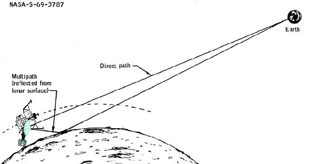 ...and when it is oriented toward the moon it only receives the signal reflected by the moon, and not the one directly coming from the earth. |
 Besides, when you receive a radiowave on earth, it is reflected from different directions, and it does not prevent you from correctly receiving it. Even if it comes from different sources, it is the same identical signal, which is demodulated to obtain the information it contains. |

 They say: "Operation of the S-band high gain antenna in the narrow beam mode resulted in a decrease of approximately 10 to 12 dB in both uplink and downlink signal strength on several occasions." |
 The signals received by the dishes are compared in order to determine the direction of the signal transmitted from earth, and this comparison allows to automatically orient the antenna toward the direction of the signal. When there is a loss of power in the signal, it would come from a temperature sensitive circuit connection which would make that the the signal received on one dish would be dephased of 180�; this would create a shift of 5�, and a loss of gain of more than 10 db. It would be the exposition to the sun which would create an overheat causing this malfunction. |
But the exposition to the sun is not very different along the revolutions; a revolution is indeed around two hours long, and the lunar day is almost one month long. So, why so much difference in the diagrams of the gain? |
 Furthermore, on the diagram of Revolution 13, in the part of the diagram on which the gain shows brutal drops, there is a peak which goes above the optimal value of the gain; how is it possible, how can the gain be better than optimal? |
 The fact that the signal could lose more than 10 db was sometimes forcing the astronauts to switch the antenna to manual. (on my animation I am exaggerating the oscillation of the antenna, this ocillation is only for an illustrative purpose, only to show that it is stronger than normal). |
 Now, if the dish which causes the problem (i.e. which is connected to the failing temperature sensitive connection) is eliminated from the signal comparison, the shift is consistently reduced from 5 degrees to 1 degree, and the loss of gain becomes only 1.5 db instead of more than 10 db if the failing dish is kept in the signal comparison. (the oscillation I show on this animation does not exactly reflect the reality, only purposed to show the important difference between the failing dish kept in the signal comparison, and this one eliminated). |
 I show here with a red line a loss of gain of 1.5 db relatively to the optimal gain in the different diagrams of the gain when there was a loss of gain because of a failing temperature sensitive connection causing the dephasing of the signal from a dish. And we can see that, if the failing dish was eliminated from the signal comparison, it would allow to have a quite good reception of the signal, perfectly acceptable. So, why not allow the astronauts to eliminate a failing dish in case that this problem occurs, rather than switching to manual? |
  Here the problem was intermittent, but imagine the problem would have become permanent instead of only being intermittent? It would have forced the astronauts to remain on manual when they wanted to have good communications with the earth. |
 If the astronauts had the possibility of just eliminating the failing dish in the signal comparison, it would allow them to keep the automatic angle pointing mode, and have acceptable communications with the earth, without caring about reorienting the antenna toward the earth themselves. |
 In Apollo 12, the mission report says that the NASA engineers had devised a system which was allowing to remove the noise from the voice when the astronaut was talking in the microphone. |
 The principle was that a pure noise was generated and subtracted from the "Voice+Noise" signal, thus removing the noise from the "Voice+Noise" signal and allowing to obtain a pure voice, not polluted by noise. |
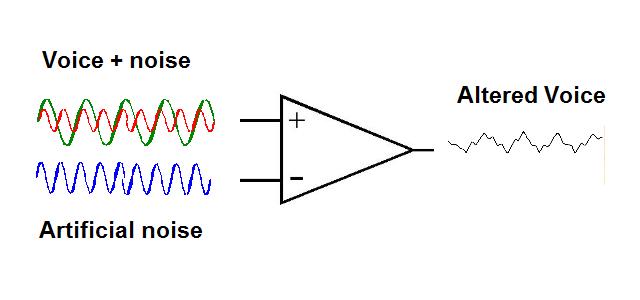 The problem is that, when the headset was not properly adjusted, the level of the signal "Voice+Noise" could not be what expected, and the pure noise, instead of just removing the noise in the signal "Voice+Noise", was also removing a part of the voice, thus altering the voice. So, they were recommending the astronauts to well adjust their headset, so this would not happen, and the noise could be correctly removed by this system without altering the voice. |
But this is completely ridiculous. In my schema, I have simplified the voice by representing it as a single wave, and also the noise. |
 In reality the voice is made with plenty of waves of different frequencies and amplitudes called harmonics. Voice synthesis works by creating these harmonics and adjusting the amplitude of the different harmonics. The noise is also made with different waves of different frequencies and amplitudes, and these frequencies and amplitudes are all random. |
It means that it is completely illusory to try to reconstitute the noise which is mixed with the voice; the reconstituted noise will never match a noise of which the harmonics have not only random frequencies and amplitudes, but also varying ones. Even if the headset is perfectly adjusted, this system will degrade the voice without removing the noise which goes with (and even increasing this noise). |
 This weird idea that the noise could be eliminated with a fabricated noise is once again a good joke from the engineers! |

 In the mission report of Apollo 13, they talk about shaft fluctuations in the Zero optics mode, and they show this schema for the "Zero optics mode circuitry". In fact this schema is completely incoherent for the reasons I am going to explain. |
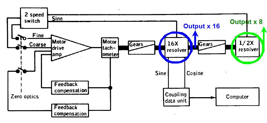 First we see that the output of the tachometer is first multiplied by 16 (in frequency), and then divided by 2, giving a tachometer signal multiplied by 8. |
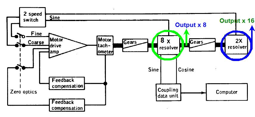 This is illogical: It would be simpler to first multiply the tachometer signal by 8, and then to multiply it by 2, to obtain a tachometer signal multiplied by 16; we would obtain the two same signals (in reverse order), but in a simpler way, using less electronics. |
 Then we see that a sine transformation is applied to one of the multiplied signals (but not the other one); it makes no sense to apply a sine transformation to a pulsed signal. Then the two multiplied signals are inputs to a 2 speed switch block which must output a single signal. Instead of that this switch block outputs two signals which both come into the motor drive amp. |
 The proof that this is an incoherence is that, in the same interface of Apollo 12, this block outputs a single signal, as you can see. But that does not mean that the one of Apollo 12 is normal, it is delirious too, but in a different way. |
 Then there is a feedback compensation which is permanently applied, but there is also another one which is applied in case that the zero optics switch is closed; the second one is useless, as there already is the first one. |
 Then there are two signals inputted into the CDU from the 16X resolver. The CDU (Coupling Data Unit) is a device which allows to transform data signals into an usable form for the computer; here it consists in counting the tachometer pulses, and giving the corresponding count to the computer. There are two input signals, for the phase difference between these two signals allows to know in which direction the motor is turning, and thus if the pulses must be counted or decounted. But what is abnormal is that: 1) sine and cosine functions are applied to the pulsed signals, which makes no sense. 2) the inputs should directly come from the tachometer output, and not the multiplied signal. |
 The motor drive amp output comes into a tachometer (circled in red). But what is a tachometer? |
 A tachometer is a device which allows to generate pulses from the rotation of a wheel. Its resolution is characterized by the number of pulses generated per full rotation of the wheel. It allows to measure the rotation of the wheel by counting the number of generated pulses. |
 It also allows to measure the speed of a spinning wheel; the faster the frequency of the generated pulses, and the faster the rotation of the wheel. It is used to measure the speed of cars, since the rotation speed of the wheels is related with the speed of the car. |
 It also allows to follow the displacement of a conveyor; to know how much a conveyor is moved, the number of generated pulses read is multiplied by the circumference of the tachometer wheel, and divided by the number of pulses per full rotation of the wheel, to finally obtain the distance that the conveyor has moved. |
 This principle is also used in mechanical mouses. As you move the mouse, a spherical ball turns which makes turn two wheels disposed perpendicularly, which each send pulses to an electronic circuitry as they turn, which are counted or decounted to update the position in the two directions that the mouse moves. |
 This is how the computer can know how you move the mouse and update the position of the mouse cursor on the screen. |
 If we correct the interface to eliminate all the anomalies which have been show, we obtain this: - The signal is first multiplied by 8, and then by 2, to obtain the two multiplied signals. - The multiplied signals are inputted into the speed switch block, without applying a sine transform to one of the signals, and only one output comes out of this block. - The redundant feedback compensation is suppressed. - the outputs of the tachometer directly come into the CDU, without sine and output transform being applied to them. But, if this new interface is more logical than the original one, it does not mean that it is correct for as much. |
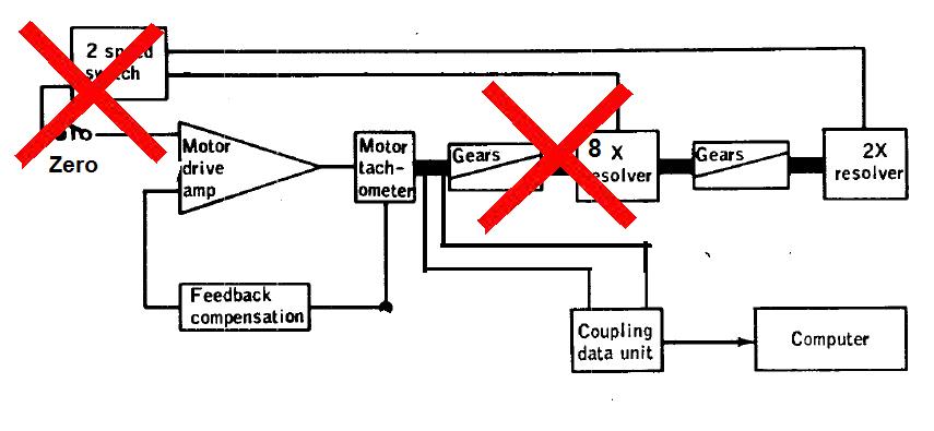 First the zero optics cannot be obtained just by looping the multiplied signals on the motor drive amp. Indeed what does that mean making the zero on the optical system? It means that, when the optical system is centered, the system must be warned that it must take it as a reference, and count or decount pulses from this reference. It certainly cannot be achieved just by looping the multiplied tacho signals. So, the multiply blocks of the tacho signal are useless, and their output signals must not be looped back on the motor drive amp. |
 Then what does mean the feedback compensation, and when is it used? The feedback compensation is used when the command must produce a desired effect, and the produced effect can be measured; the desired effect and the measured effect are then differentiated and the difference is used to correct the command till the measured effect matches the desired effect. |
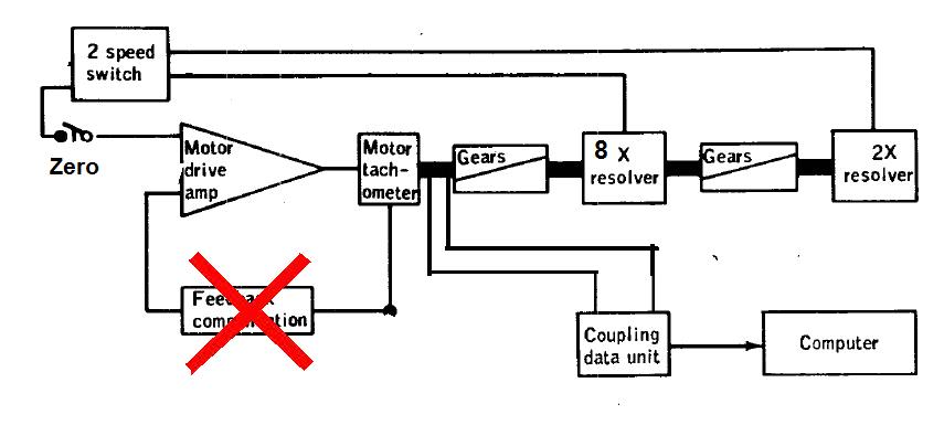 But, in the case of the optical system, the motor drive amp does not produce a command, but just allows to generate pulses, via the tachometer, which are counted to measure the displacements of the optical system. So, there is no point using a feedback compensation in this context. |
 So, finally, after having eliminated the useless parts which should not be there, we obtain this final interface: - The tachometer generates pulses on two signals, of which the phase difference allows to know in which direction the motor wheel is turning (so to know if the pulses must be counted or decounted); these two signals are inputted into the CDU which counts (or decounts them); the computer can read the count via an I/O instruction. - A zero switch (or pushbutton) is connected to the CDU; when this switch is set, it sends a signal to the CDU which allows to clear the pulse counter of the CDU, so that, when the computer reads zero on the counter, it knows the optical system is currently centered. Now we have a coherent optical interface. |

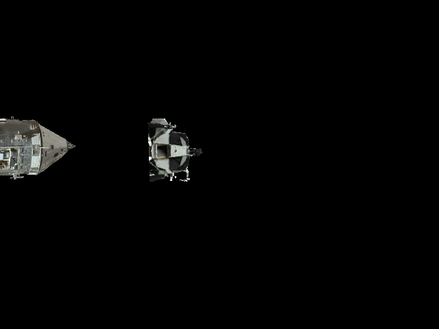
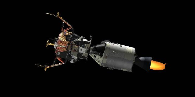
After the translunar insertion, made by the S-IVB (the last stage of the Saturn rocket, containing the command module and the lunar module), the S-IVB was opening its doors, the command module was getting out of it, moving forward, making a turnover maneuver, going back to the S-IVB, docking to the lunar module which still was in the S-IVB, extracting it from the S-IVB, and the whole spaceship was then starting its travel toward the moon. Notice that, in my animation, I have represented the lunar module with its legs already deployed, while in fact they were still stowed. |
 In Apollo 14, the command module would have made five unsuccessul attempts to dock to the lunar module, and it is only the sixth one which succeeded, and allowed the command module to extract the lunar module from the S-IVB. |
 This is the schema they show for the probe assembly of the command module. They show the probe's arm in its locked position, and, in dotted lines in its cocked position. They say that all the parts of the probe operated normally, and they see no rational explanation for its abnormal behavior. They finally come to the conclusion that the problem would have been caused by external contamination, for the probe would have normally worked after the sixth successful attempt, including when the lunar module docked to the command module after its return from the lunar surface. |
 In fact, there is an explanation, and it comes from the area I have circled. The toggle lays on the locking roll pin on the schema, but it is because the probe's arm is represented in its locked position. |
 But the toggle is articulated in such a way that, when the probe's arm is in its cocked position, the toggle's extremity moves down at the level of the roll pin. |
 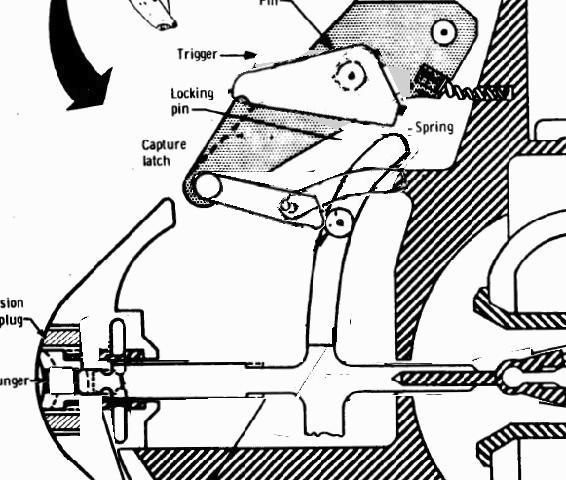 The result is that, when the arm is extended, it is blocked by the lower extremity of the toggle, and can go no further; it can't reach the locked position. |
 So, on the five first attempts, the toggle blocked the arm, and received successive shocks from the arm's roll pin. |
 Because of these successive shocks, it became more and more chipped. |
So, after the successive shocks received from the roll pin, the shape of the toggle's extremity may have changed enough (or the circumference of the roll pin may have been eroded)... |
 ...so that the roll pin could pass under the toggle, which was allowing the arm to move forward till its locked position. |
That's what happened in the multiple docking attempts of Apollo 14. The five first unsuccessful attempts allowed to create the conditions for the roll pin to pass under the toggle. |
 And from that moment, the roll pin could always pass under the toggle, which means that the arm could always reach its locked position when extended. That's why the docking of the lunar module to the command module succeeded at the first attempt when it returned from the lunar surface. |
And this explanation is much more likely than the one of an external contamination. |
 Of course, the engineers are not so dumb that they could not have done things properly so to avoid this problem. This is an obvious hint they give about the fakery. |

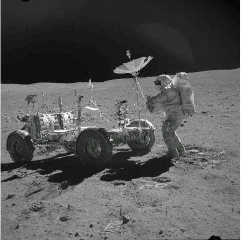
 In Apollo 15, the signal of the lunar rover was lost 40 hours after the lunar module ascent. They suspected a problem in the power distribution of the LCRU (Lunar Communications relay unit). They show this schema for the power distribution of the LCRU. |
 To verify the loss of the 16.5 volt power, they sent a voice from the ground, and they tried to receive the VHF signal on a 150 foot (45 meters) VHF antenna. |
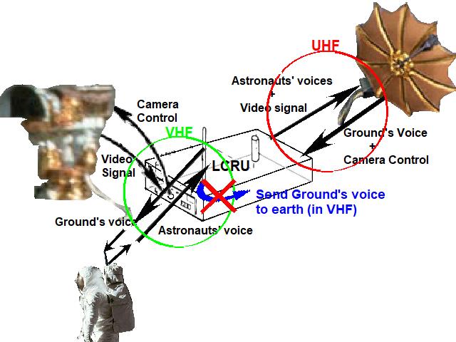
 The LCRU is connected to the high gain antenna, sends to it an UHF signal which contains the video signal of the camera, and the voices of the astronaut, received in VHF on the omnidirectional antenna of the LCRU, and the high gain antenna transmits this UHF signal to the earth. Conversely, the high gain antenna sends to the LCRU an UHF signal received from the earth, which contains the ground's voice and the camera control signal; this UHF signal is demodulated, the camera control signal and the ground's voice extracted from it, the camera control signal sent to the TV camera, and the ground's voice sent to the astronauts through the VHF omnidirectional antenna of the LCRU. |
 In order for the high gain antenna to be able to send the UHF signal to the earth, it must precisely be oriented toward the earth. That's why the TV camera does not transmit to the earth while the rover is riding, for the judders of the rover prevent the high gain from remaining correctly oriented toward the earth. At each stop of the rover, an astronaut reorients the high gain antenna toward the earth, so that the camera can film the astronauts while they are moving around the rover. |
 All the videos which are made while the rover is moving are filmed by the 16mm camera fixed at the center of the rover, and what it films is not directly transmitted to the earth, but developed on earth after the return of the mission. Besides you can see the TV camera on these videos. |
The UHF signal sent by the high gain antenna is received by a very large parabola dish on earth; the signal is sent in UHF (ultra high frequency), for a VHF signal does not have a frequency high enough to be able to go through the whole earth's atmosphere. |
 So, what they suggest is that the VHF signal of the ground's voice, sent by the omnidirectional antenna of the LCRU, and which is received by the backpack's antenna of the astronauts, could also be received on earth... |
 ...By a simple VHF antenna! |
 But, if it was that simple, why would they care to send the communications through the high gain antenna? And, since the antenna of the LCRU is omnidirectional... |
 ...The video of the TV camera could be sent to the earth even when the rover is moving! |
 The reality is that there is no way that the VHF signal of the ground's voice, sent by the little ominidirectional antenna of the LCRU, could reach the earth, and be received by a VHF antenna on earth. |
 The only way that it could have worked is that there would have been a possibility of looping the output of the signal of the ground's voice on the input of the astronauts' voices, so that the ground's voice could modulate the UHF wave, and be sent to the earth through the high gain antenna, and received, in UHF, by a very large parabola dish on earth. But this possibility had not been provided, so it was not even possible to proceed that way. |
 In other words, the test they plan to do to test the 16.5 power is just impossible to do, a total fantasy... |
...And, of course, the engineers perfectly knew it, for it is one more joke from their part! |

 In the first missions, the descent was made in one step: After the lunar module had undocked from the command module, if was initiating a descent orbit insertion maneuver (by decreasing a little its orbital speed to take the descent orbit), and, after it had reached a closer orbit of the moon, it was starting the powered descent. In the last missions, the descent was made in two steps: The whole spaceship was making a first descent orbit insertion maneuver, using the engine of the service module, and, after it had reached a closer orbit of the moon, the lunar module was undocking from the the command module, following the orbit for a while, and it was initiating a second descent orbit insertion maneuver, this time using its own engine, and, after it had reached a still closer orbit of the moon, it was starting the powered descent. |
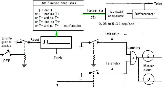
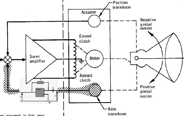
 But, in Apollo 16, there would have been a little problem with the service module, which delayed the initiation procedure to take the descent orbit "because of oscillations detected in a secondary yaw gimbal actuator on the service propulsion system engine during systems checks for the circularization maneuver." The consequence is that the powered descent would also have been delayed. |
 In the anomalies report, they give an explanation about this problem. Their analysis concluded that there would have been an electrical problem, with oscillations detected because of parasites on the looping of the rate of the positive gimbal motion back to the input of the gimbal servo. |
 But, in fact, only the gimbal's motion (colored in green), after having been converted to an electrical signal by the transducer, should have been looped back to the input of the servo. The gimbal's motion rate (colored in red) should not be looped back to the input of the servo. And it is not even an electrical signal corresponding to the gimbal's motion rate which is obtained after the transducer, but it is again an electrical signal corresponding to the gimbal's motion. In order to obtain the gimbal's motion rate, the electrical signal of the gimbal's motion must be passed through a circuit which converts it to its derivative. |
 The electronic circuit which allows to derive a signal uses an operational amplifier, and I show here how this circuit works. |
 An operational amplifier has various uses; it can be used to add currents, to subtract them, multiply them, divide them, integrate them, or derive them. It is used in analog computers; the program of an analog computer in fact consists in connecting operational amplifiers which cables, these operational amplifiers being set to either be used as an adder, a subtracter, a multiplier, a divider, an integrator, or a derivator. An analog computer is well suited to simulate the behavior of planes, but don't expect to use it to play video games. |
 A hybrid computer is an association between an analog computer and a digital computer; the analog computer is programmed with cables connecting operational amplifiers, and the digital computer is programmed with software instructions; they communicate with each other through analog to digital and digital to analog converters. I once used one to make a study on air-air missiles. |
 So, it means that, on the lower branch of the servo, an electronic circuit to convert the electrical signal of the gimbal's motion to its derivative, so to obtain its rate, should have been added before looping it back to the servo's input. Of course, it is only in the hypothesis that the rate of the gimbal's motion should have been looped back to the input of the servo. |
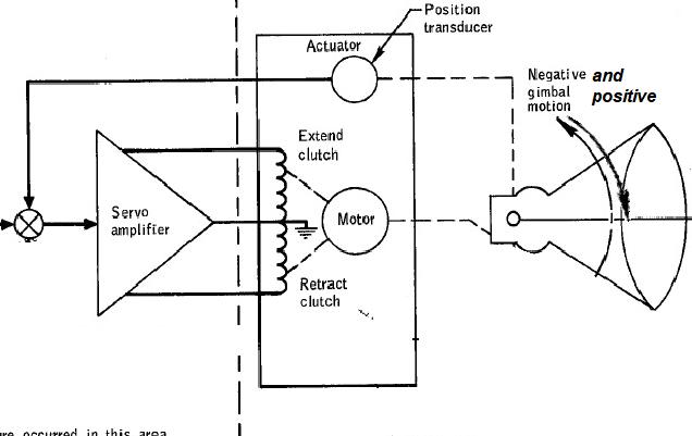 For, in reality, it shouldn't have. The lower branch of the servo should not have existed, only the upper branch. Only the gimbal's motion, after having been converted to an electrical signal by the transducer, should have been looped back to the servo's input, whether it is a positive or negative motion. |
So the explanation they give for the oscillations of the gimbal system of the service module is senseless. |
 It is obvious that it is only to add a little good suspense for those who are fond of it. |
And in the same time, give a new hint of the fakery. |

 In the mission report of Apollo 17, they say that the Command Module Pilot compared his determination of the earth's horizon differential-altitude measurement with a value stored in the erasable memory of the computer. |
 They also say that a program for cislunar midcourse navigation, located in the erasable memory of the computer, was utilized throughout the mission and was very worthwhile. |
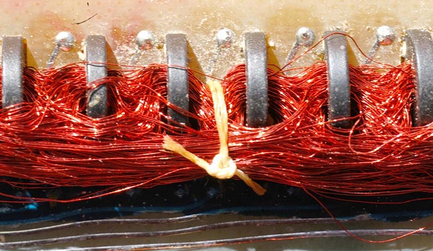
 The AGC used two types of memory: 1) The core rope memory consisted in cores in which wires could pass through, which ones were representing bits set to 1, or over which other wires could pass, which ones were representing bits set to 0. Its advantage was that it could keep its contents even when the AGC was not powered, but its disadvantage was that it could only be read, and not written. It was containing all the programs of the AGC. 2) The erasable memory was dynamically used; it could be both read and written, unlike the core rope memory, but its disadvantage over the core rope memory was that it could not keep its contents when the AGC was not powered. |
 In the sixties and seventies, the computers were big machines which were operated by specialists, and the users did not have a direct access to them. They were giving to the operators packs of punched cards that the operators were entering into the computer, and were obtaining in return listings corresponding to the result of their programs. |
 The operating system was loaded into these computers at start-up from tapes. |
 These computers also had a core rope memory, but it was only containing a boot program allowing to load the operating system from tapes. Besides these core rope memories had a too small capacity to contain the operating system. |
Moreover, the operating system was often modified to be improved and corrected, and making these corrections in the core rope memory would have been a long and painful process, while it was relatively easy to do it on the magnetic tapes. |
 In the first portable computers (like the famous Apple II), the operating system was contained in a rom (read only memory, the equivalent of the core rope memory, though, at the time, it was easier to program these roms than a core rope memory), and the user could save his programs on a cassette. But this saving process was quite slow and rather unsure. If the volume of the recording was not properly set, the program might be incorrectly recorded, and it could never be reloaded. Even if it had been correctly recorded, if the least damage was happening to the cassette, it could also never be reloaded. And, even if it was correctly recorded on the cassette, reloading it was not always succeeding at the first attempt, if the volume was not correctly set, and it had then to be done a second time. That's saying how saving the programs in this archaic way was rather painful and unsure. |
 Then, a little time later, the floppy disks have started to appear, which was making the saving process easier and more sure. These floppy disks had a rather big size, and had a smaller capacity than the current ones. Still using them was a real improvement, compared with the use of cassettes. |
 Then the size of the diskette has decreased, in the same time that their capacity was increasing. |
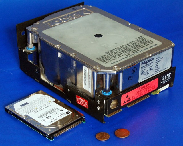 Then the hard disks have started to appear. The first hard disk I have known was rather big, and only had a capacity of 5 megabytes; it was slower and more noisy than the current hard disks, but yet it was a real improvement compared with the diskettes of the time, and it had a much bigger capacity (the diskettes of the time had less than 100 kilobytes capacity). This photo shows a hard disk of the time, and a modern hard disk, which, though being much smaller than the old hard disk, has a much greater capacity, and is much faster. |
 And, finally, we now know the USB keys, which have a great capacity, compared with the capacity of the first storage units, and which allow to easily transfer files from a computer to another one. |
 It was not possible to store data in advance into the erasable memory, for the AGC was not powered at the launch of the Saturn rocket, but only a little later (according to the mission report). |
 All the technology we have previously seen was not existing in the time of Apollo, save the possibility of loading data from a cassette reader. But loading data from a cassette reader would have been rather hazardous, compared with the safety of the core rope memory, for there was no guarantee that it would work, and, unlike the core rope memory, the magnetic tape could be harmed by radiations. So, this facility had not been provided by the engineers. |
The program could also have been transferred from the core rope memory to the erasable memory, but it makes no sense, for the program could also be directly executed in the core rope memory, and the erasable memory had much less capacity than the core rope memory (16 times less). The erasable memory was also used for allocating memory resources used by the programs, and we know that the AGC fucked up in the descent of Apollo 11 because it had become short of memory resources. |
 So, the fact that the program for cislunar midcourse navigation would have been located in the erasable memory instead of the core rope memory makes no sense... |
...and is once again an obvious joke from facetious engineers! |

