THE ABORT FIX OF APOLLO 14 (AND THE 1202 ALARM OF APOLLO 11)

 In Apollo 14, at the beginning of the descent of the lunar module on the moon, the astronauts saw the abort stage button intermittently flicker; an astronaut gently tapped on it, and it went off. |
 The problem would come from a spurious signal in the abort logic interface. |
 The Abort Stage button is the Abort button which allows to drop the descent stage before returning to the command module, while the Abort button simply aborts the mission and allows to return to the command module with the descent stage still attached. The Abort stage button is ignored before the powered descent, for it is still time to come back to the command module with the descent stage attached. |
But, in the powered descent, the spurious abort signal might command the separation of the two stages of the lunar module without the astronauts having asked for it by pressing the Abort Stage button. It means that, if no solution is found for this problem, the mission can not be carried on and has to be immediately aborted. |
 So the astronauts reported this problem and asked for help to know how to solve this problem. Houston then called the MIT so they could devise a solution for this problem, allowing the powered descent to be performed without being interrupted by an unwanted abort. |
 So the MIT team quickly devised a modification to solve this problem, and sent it to Houston. |
 Houston then telemetered this magical solution to the lunar module, which was consisting in sequences of keys that the astronauts had to type on the keyboard of the AGC....but not immediately, at the right moment instead, as explained in a link. Link to the explanation of the abort fix of Apollo 14 |
 Just after the engine is started, a bit in memory, called "LETABORT", is set within a very short time of 0.2 second; from that moment, if nothing is done, the spurious abort signal can command the separation of the two stages of the lunar module. |
If the astronauts wait for the engine to start, the LETABORT bit will be set very fast, and it would take time for the astronauts to type the sequence to reset the LETABORT bit, and meanwhile the spurious signal could command the separation of the stages. So, just after the ignition routine has started, the astronauts are instructed to type a command which allows to change the program number from P63 (which is a program of the powered descent) to P71 (which is not a program of the powered descent), so that the abort stage command cannot be taken into account when the LETABORT bit is set by the Engine Start. According to the description of the problem, the command that Edgar Mitchell would have had to type was: VERB 21 NOUN 01 ENTER 1010 ENTER 107 ENTER |
 The description of the problem states that, because the program registered in MODREG has been changed to a program which does not belong to the powered descent, the ignition routine will not set the engine to full thrust after 26 seconds, like it normally should. So, the procedure to be followed is to wait for the 26 seconds after the start of the ignition routine... |
 ..and manually set the throttle command to maximum in order to do what the ignition routine would have normally done if the current program had not been changed... |
 ...that is set the engine to full thrust. |
Then Mitchell must type a command to set a ZOOMFLAG bit, which should normally have been done by the ignition routine (if the current program had remained P63), so to logically command the full thrust. This command is: VERB 25 NOUN 7 ENTER 101 ENTER 200 ENTER, 1 ENTER Note that the address "101" is specified as three octal digits, whereas the documentation of the DSKY specifies that a machine address must mandatorily be specified as 5 octal digits. The bit mask "200" is also only specified as 3 octal digits, whereas a bit mask must normally be specified as 5 octal digits, for there are 15 bits in a word, and each octal digit encodes 3 bits of the word. Then Mitchell types a command to reset the bit LETABORT to 0, which is: VERB 25 NOUN 7 ENTER 105 ENTER 400 ENTER, 0 ENTER Finally Mitchell must still enter a command to restore the program number to P63 (normal program of the powered descent), which is: VERB 21 NOUN 01 ENTER 1010 ENTER 77 ENTER That makes a total of 4 sequences of keys (counting the sequence which has been made just after the start of the ignition routine). After the normal ignition program has been restored, the LGC is supposed to have the control of the thrust again. |
 Finally the description of the problem says that Shepard puts the handcontroller of the thrust control back to minimum, in order to let the guidance take the control of the thrust again, so to let the guidance routine take over the engine, as they say (after the braking phase, the guidance routine must decrease the thrust). But it is completely absurd, this is not what he must do, for the manual control of the thrust and the automatic control by the LGC are not cumulative, but exclusive; it is not one and the other, but one or the other. |
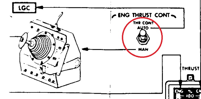 The thrust is controlled by either the handcontroller or the LGC, but not both in the same time. When the handcontroller has the control of the thrust, the LGC does not have the control on it at all (thrust control switch on "MAN" position), and, when the LGC has the control of the thrust, the handcontroller has no action whatsoever on it (thrust control switch on "AUTO" position). |
 Shepard must absolutely not set the manual control of the thrust to minimum, but simply change the thrust control switch from Manual to Auto, in order to give back the control of the thrust to the LGC (in which case the handcontroller is not at all taken into account). |
If he just manually sets the control of the thrust to minimum, the thrust will remain at minimum, for the LGC will not have the control of the thrust, as the thrust control switch is still on the "MAN" position, which means that the powered descent cannot normally happen. |
 In reality this is completely absurd. Indeed, the fact that the ignition routine sets the LETABORT bit, which is part of its treatment, shows that it is normally running. Once that the ignition routine has started, it is obvious that it is going to do its full normal treatment, that it is not going to check the current program number not to make a part of its treatment. So, what the astronauts should have done is to wait for the engine to start, and they would have known at this moment that the bit LETABORT had been set, and then simply type the command to reset the bit LETABORT, and the command to restore the program number to P63. That would have made three sequences of keys at total, instead of four, and Shepard would not have had to manually control the thrust, which would have been automatically done by the guidance routine. The fact that the ignition routine would not have automatically controlled the thrust is an excuse that the engineers have made up to justify the fact that Shepard would have had to manually control the thrust, which allowed to create an anomaly with Shepard not giving back the control of the thrust to the LGC at the end of the maneuver, with the consequence that the powered descent could not normally happen. |
 So this useless complication is just a good joke from the engineers. |
 If the astronauts had been able to modify the program in the core rope memory, they would have prevented the ignition routine from setting the LETABORT bit, and, fhis way, the lunar module would immediately have been protected against an unwanted abort stage commanded by the spurious abort signal after the ignition routine started, without the astronauts having to make this weird procedure (which moreover is incorrectly ended). |
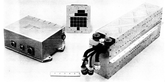
 But that would have supposed that the astronauts would have been able to modify the program in the core rope memory, The core rope memory was programmed by female workers making wires go through ferrite cores or overpass them according to instructions which were given to them. Each wire was representing a bit. After they had made their work, the core rope memory was tested to see if it had been correctly weaved. If ever there was even a single error in a bit wire, this wire had to be completely removed and weaved again. |
 We hardly see the astronauts do this work in the lunar module. So the only resource which was left to them was to apply a procedure which was not perfect, was not offering a total guarantee of success, and which moreover was uselessly complicated as it is described. |
 And that's not all, for the description of the problem gives other details which are completely delirious. They say that the routine has corrected the calculated height with only a portion of the difference between the height measured by the radar, and the one measured by the accelerometers, that they call "DeltaH". |
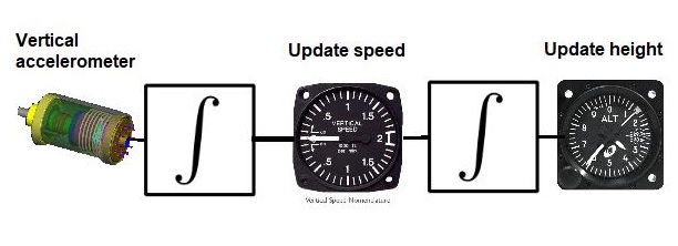 But there is no such thing as the height measured by the accelerometers. The accelerometers don't directly give the current height. The calculated height is precisely updated from the readings of the accelerometers, by double integration (a first integration to update the vertical speed from the reading of the vertical accelerometer, and a second one to update the current height from the vertical speed). |
They then say that, at 50000 feet, they add 0% of this portion, and 35% of this portion at 10000 feet. Explain me how it is possible to increase of 0%? And how much of this portion do they add between these two heights? |
Now I am going to explain why it makes no sense to correct the calculated height with only 35% of the difference with the height obtained from the radar. An accelerometer is not perfect, there always is a slight bias error. To update the calculated height, this error goes through a double integration, and this double integration tends to make this error diverge. If the calculated height is corrected with only 35% of the difference with the height obtained from the radar, which is more precise, only 35% of this error is compensated, there remains 65% of it in the calculated height. |
They then say that, if the program register does not contain P63, the routine would think that the current program was P66, and would incorporate the full 35% of the DeltaH; so the routine does not even check the current height? They say that the problem on the landing radar would come from a scale bit which would have changed 38 seconds before one of the procedures of abort masking would have been entered; explain me the relationship between a problem on the landing radar and a procedure of abort masking? The whole description is a heap of nonsense. |
 I have got interested in the way that the abort was processed in the program of the AGC, and how the LETABORT bit was taken into account, how it was making a difference between this bit being set or reset when an abort was requested. In the whole program of the AGC, there is a unique program where this bit is considered (apart from being cleared in the beginning of the descent program), that is in the process of the programs P70 and P71 (LEM LM DPS Abort, and LEM LM DPS abort). And I show here the unique sequence where this bit is tested. I am going to detail this sequence, step by step. |
 This sequence tests if the LETABORT bit (corresponding to LETABBIT) is set. If it is, the result will not be null, otherwise the instruction BZF LANDISP (branch if accumulator is null) makes a branch to LANDISP, which corresponds to proceed to R10 according to the comment. |
 So, if the LETABORT bit is set, we continue in sequence. MODREG contains the current program number; the instruction "CS MODREG" puts the negative contents of MODREG into the accumulator, which means that, if the current program is P71, the accumulator now contains -71. The instruction "AD 1DEC71" adds 71 to the accumulator, which means that, if the current program is P71, the accumulator now contains 0. The instruction "BZF LANDISP" makes a branch to LANDISP if the accumulator is null, in other words, if the current program is P71, according to what has been said. |
 So, is the current program was not P71, the program continues in sequence. The instruction "READ CHAN30" reads the contents of channel 30. |
 The channel 30 is described in the handbook of the lunar module. The two interesting bits are the first bit, which is set if an abort using the descent engine has been requested (by pushing the ABORT button), and the fourth bit which is 1 if an abort using the ascent engine has been requested (by using the ABORT STAGE button). |
 The instruction "COM" complements all the bits of the value read in channel 30 (that is the bits set to 1 become 0, and vice versa); the result is put into the registre L with the instruction "TS L". Now the first bit of the accumulator is 0 if an abort has been requested, and the fourth bit is 0 if the request has been made with the ABORT STAGE button. The instruction "MASK BIT4" only keeps the fourth bit of the accumulator and puts all the other bits to 0, so, the accumulator is now null if an abort has been requested with the ABORT STAGE button. The instruction "CCS A" tests the accumulator, and executes the first next instruction if the accumulator is positive, and the second next instruction if the accumulator is null. So, if an abort has been requested with the ABORT STAGE button, it is the second next instruction, "CS MODREG", which is executed, the next instruction is skipped. |
 The program continues thus in sequence. MODREG contains the current program number; the instruction "CS MODREG" puts the negative contents of MODREG into the accumulator, which means that, if the current program is P70, the accumulator now contains -70. The instruction "AD 1DEC70" adds 70 to the accumulator, which means that, if the current program is P70, the accumulator now contains 0. The instruction "BZF LANDISP" makes a branch to LANDISP if the accumulator is null, in other words, if the current program is P70, according to what has been said. |
 So the program continues in sequence if the current program was not P70. The contents of the channel 30 has been put into the register L AFTER having been complemented (that is the bits 1 set to 0 and vice versa). It means that the first bit of L contains 0 if an abort has been requested. The instruction "CA L" puts the contents of L into the accumulator; it means that the first bit of the accumulator is 0 if an abort has been requested. The instruction "MASK BIT1" only keeps the first bit in the accumulator, and sets the other bits to zero; as the first bit was 0 in case of abort request, it means that the accumulator is null after this instruction in this case. |
 The instruction "CCS A" tests the accumulator, and executes the first next instruction if the accumulator is positive, and the second next instruction if it is null. It means that, if an abort has been requested, it is the second next instruction "TCF LANDISP" which is executed, as the accumulator is currently null (contrary to what the comment says). In other words, if an abort has been requested with the ABORT button, the program will proceed to R10 (LANDISP). |
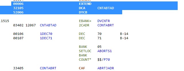 So, if the ABORT STAGE button has been pressed and the bit LETABORT is set, the program continues at the label P70A. In it, we find this sequence of instructions. The instruction "DCA CNTABTAD" loads the contents of CNTABTAD, that is the double address of CONTABRT, into the pair of registers A,L. The double address of CONTABRT means its address in its bank, and its memory bank. The instruction DTCB exchanges the pair of registers A,L with the pair of registers Z,BB. So, after this instruction, Z contains the address of CONTABRT, and BB its memory bank. Z is the program counter, that is the address of the current instruction to be executed, and BB is the memory bank register; it means that the next instruction which is executed after DTCB is the instruction at the label CONTABRT. But, as CONTABRT is in the same memory bank, it would have been much simpler to replace this sequence of instructions with the simple instruction "TCF CONTABRT". An useless complication which wastes memory space. The sequence between DTCB and CONTABRT is skipped; it contains two declarations of values (1DEC70 and 1DEC71) which are not necessary, for these values could have been directly used without these declarations. |
 In this sequence, we find further in the program, the instruction "CAF ABRTJADR" loads the contents of ABRTJADR, that is the instruction "TCF ABRTJASK", into the accumulator. The instruction "TS BRUPT" stores the accumulator into the register BRUPT, which means that BRUPT now contains the instruction "TCF ABRTJASK". The instruction "RESUME" makes a return from interrupt; the documentation says that the instruction stored into BRUPT is then executed, which means that the instruction "TCF ABRTJASK" is executed, and this instruction makes a jump to ABRTJASK. But ABRTJASK just follows in sequence, which means that this sequence is useless; once more a waste of instructions. |
 Then follows a sequence of instructions playing with variables, obviously making an useless work. We find this sequence of instructions; this sequence is also used in the master ignition program, "burn baby burn", (I'll detail it when I talk about this program), and it allows to set the descent engine on. But the descent engine is already currently on, so this sequence is useless, and once more a waste of instructions. |
 Then we find this sequence of instructions. This sequence allows to make a fresh restart. But this is only to be done in case of blocked situation, and the AGC is not currently blocked, so this sequence is useless (once more). |
 Then we find a sequence of instructions using macro-instructions, and we find what we can also find in other programs: Lines with two macro-instructions on the same line, which is illegal, and should have been rejected by the compiler. |
 Finally the program ends in switching to the ascent program, but after having made plenty of useless instructions, and even used illegal instructions. |
 But the problem is that the Abort Stage button will not work in the descent, which means that, if it is not possible to land on the moon (craters everywhere), the lunar module will crash on the moon when the fuel is exhausted, as the return to the command module is impossible. separation of stages is impossible. |
 Some think that, since it was not possible to make the abort with the AGC, the AGS (Abort Guidance System), the secondary computer, simpler than the AGC, could be used for that purpose. But the AGS was only intended to be used in the ascent, not in the descent. And the AGS also uses the ABORT STAGE button for the separation of stages, so it has the same problem with the spurious signal in the abort interface. |
 And also the AGS is not immediately ready for use after the control has been given to it, it needs preparation. Its documentation says that it needs at least 30 minutes of preparation prior to lift-off, which excludes using it for the abort when flying over the lunar surface to find a safe spot to land on. |
 But the best is that the ABORT STAGE button was directly an input of the LGC. |
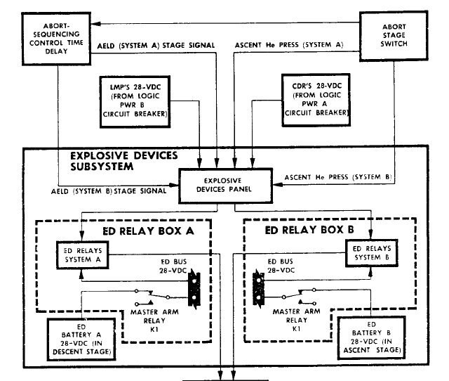 And the ABORT STAGE button was directly triggering the explosive system, the AGC could not prevent it from doing it. In the channels which were allowing the AGC to communicate with the LGC, there was no bit which was allowing the AGC to allow or inhibit the separation of stages. In fact, all the LETABORT bit was doing was to allow the descent program to be replaced with the ascent program. |
But, if the ABORT STAGE button was separating the two stages, and the AGC was remaining in the descent program because resetting the LETABORT bit was preventing the AGC from switching to the ascent program, it was worse than if the AGC had proceeded to the ascent program, for the ascent program would at least have allowed the lunar module to return to the command module. |
 While, if the AGC goes on controlling the descent engine while in fact this one has separated from the lunar module, sure the lunar module will make the descent on the moon...but the landing will be a little brutal! |
It is more than obvious that this Abort fix of Apollo 14 was nothing but a big joke of the NASA engineers. |
 There is another mission in which the NASA engineers have created an absurd problem. It is the mission Apollo 11, in which the famous 1202 alarm occurred. |
 Initially the radar switch was on the LGC position, and, in this position, everything was OK, the AGC was receiving normal radar pulses. |
 But Buzz Aldrin would have put this radar switch on the "SLEW" position. The dialog says that it was because of an erroneous indication of the checklist, but he would have given an other explanation, suggesting that it would have been his own initiative. |
 In this position, the mission report says that two dephased signals of high frequency would have created artificial fast pulses which had nothing to do with the real radar input; as the creation of these fast radar pulse was internal, and not external, it could have been tested on earth, and so the engineers could not have ignored it, it could only be intentional. |
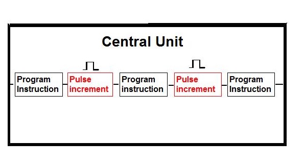
 The problem is that, unlike all the other computers, the processor of the AGC was counting itself these pulses, with what they call "hidden instructions", that is instructions which run independently of the current program, but which prevent an instruction of the current program from being executed each time that a "hidden" instruction is executed. |
 This means that the execution time of the periodical guidance task is not determined, it can vary according to the frequency of the hardware pulses that the AGC has to count. When the AGC receives normal pulses, the guidance task can still finish its work in time. |
 But, when the AGC started receiving the very fast radar pulses, it has started to take too much time to count these radar pulses, which means that the guidance routine was taking more time to finish its work, for being too much pertubed by these fast radar pulses. |
 The consequence is that the guidance task, because of these exaggerated perdubations, could no more finish its work in time, and there was an accumulation of guidance tasks waiting to be executed, as it was automatically started every two seconds. |
 The result was that there was a moment that all the available resources had been drained out, and, at that moment, the computer had to be restarted, with the light of the 1202 alarm going on. It is obvious that, with a computer working so erratically, it could no more do its normal work. |
 What's ironical is that this situation could perfectly have been avoided. Indeed, no normal processor counts itself hardware pulses. In all normal systems (including the one of the Saturn rocket), the hardware pulses are always counted by electronic counters, and an electronic counter is rather easy to do with transistors (as this schema shows), and even an electronician beginner can make one. |
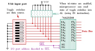 And the count of pulses of the electronic counter can be read by the processor with an IO read operation. |
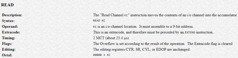 And precisely, the AGC had an IO read instruction, which means that it could perfectly have read the count of pulses from an electronic counter counting them. |
 So, instead of using the normal standard procedure, i.e. making an electronic counter count the pulses, and read the count of pulses from it with an IO operation, which would have ensured that the execution time of the guidance routine would have been constant, and would not have been increased by the radar pulses, whatever the frequency of these radar pulses... |
 ...The AGC was counting itself these radar pulses (with "hidden instructions", which was a unique specificity of the AGC), which means that, the faster the radar pulses, and the more the guidance routine was slowed down, which could have a critical effect when these radar pulses were very fast. |
 And the problem of the 1202 alarm could have immediately stopped if the ground had instructed the astronauts to put the radar switch back on "LGC"; but, no, the ground just told the astronauts to ignore the problem and proceed, with the consequence that the 1202 alarm (or 1201 alarm) could happen again. |
In other words, as well in the Apollo 14 mission and the Apollo 11 mission, the engineers have created an insane situation which should never have happened, which was handled in an aberrant way, and never the engineers would have created this type of situation in normal missions, they would never have taken such insane ricks. |
 The only possible conclusion is that the engineers are sending us very clear signs that the missions were not real. |
This part talks about the intervals between the occurences of the 1202 alarm which happened in the descent of Apollo 11. When the Radar switch was put on the SLEW selection, an interference between two dephased sources of same high frequency was producing very fast pulses, which had nothing to do with the normal radar input. These pulses have a fixed frequency. Because the processor of the AGC was counting itself these fast pulses, instead of having them counter by an external circuit, it was taking too much time counting them, and the periodical guidance task could no more finish its work in time. The consequence is that, when the delayed guidance routines had drained all the available resources, the computer could no more run and had to be restarted; then the 1202 alarm was displayed (or it could also be the 1201 alarm which was of the same type). As the fast pulses were keeping arriving at the same frequency, as long as it was the same program running in the guidance routine, the guidance routines were delayed at the same tempo, which means that the interval between the 1202 alarms should remain constant, or close to it. This is what we are going to check.  The first 1202 alarm arrives as program P63 is running, and is at time 102:38:22  The second 1202 alarm arrives with the same program, at time 102:39:02. There is 40 seconds difference with the previous 1202 alarm.  Then there is a program change at 102:41:32, two minutes and 30 seconds (150 seconds) later, with the same program running meanwhile and no 1202 alarm occurring, while, logically, as there was 40 seconds between the two previous alarms, there should have been at least 3 other 1202 alarms.  Then there is a 1201 alarm (same type as 1202) at time 102:42:18, that is 46 seconds after the program P64 has started running.  At time 102:42:43, there is a 1202 alarm, that is 25 seconds after the previous 1201 alarm, while there was 46 seconds between the start of the program P64 and the previous 1201 alarm.  Then, at time 102:42:58, there is another 1202 alarm, that is only 15 seconds after the previous 1202 alarm; there is a clear acceleration of these alarms.  At time 102:43:22, there is a change of program to P66, 24 seconds after the previous 1202 alarm, while there only was 15 seconds between the two previous 1202 alarms.  And finally, at time 102:45:40, there is the engine off, without a new 1202 alarm having occurred. So, what have we seen in the previous examples? That, while the 1202 alarm should happen at regular intervals as long as the same program is running in the periodical guidance routine, it is far from being the case; we can observe a consistent irregularity. |
 When the 1202 alarm was occurring, a special procedure "BAILOUT" was automatically called. The code of this procedure is documented, I give to link to it in the description of this video. Of course I have got interested into its processing, and I have not been disappointed, for it is full of surprises, and a stone added to the moon hoax. |
 This description is a little technical, and may be difficult to understand for non programmers, but I think that those who have some knowledge of programming will appreciate it. |
 Fasten your belt anyway, for it is high-flying! |
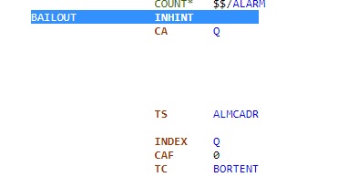 This is the entry point of the procedure BAILOUT. The first instruction which is executed, "INHINT", inhibits all interrupts, which means in particular that the display is frozen, and the keyboard does not respond. |
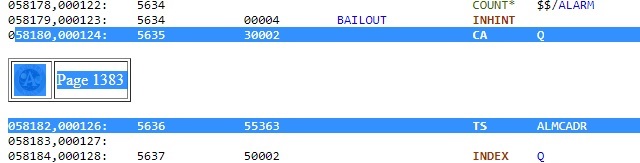 The instruction "CA Q" puts the contents of the register Q into the accumulator, and the instruction "TS ALMCADR" puts the contents of the accumulator into the variable ALMCADR. The register Q contains the return address of the procedure BAILOUT; in other words, this couple of instructions puts the return address of Bailout into the variable ALMCADR. The AGC has no stack, which means that, each time that a procedure is called by another procedure, the contents of Q is replaced with the return address of the new procedure. |
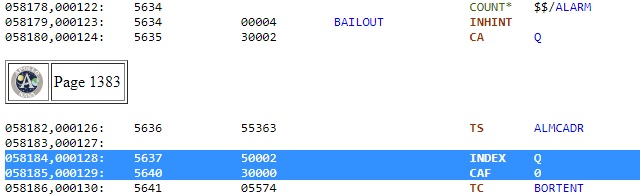 The instruction INDEX makes that its operand is added to the operand of the next instruction. So the couple of instructions "INDEX Q", "CAF 0", makes that the contents of the register Q plus zero is put into the accumulator; in other words the contents of Q is put into the accumulator. Notice that this was more simply made by a previous instruction "CA Q", and morever, it is even useless, for the accumulator was still containing the contents of the register Q, as it has not been changed meanwhile. So a couple of instructions which is totally useless and could have been avoided. |
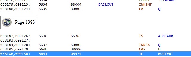 The instruction" TC BORTENT" calls the procedure "BORTENT"; the return adress, that is the address of the instruction following this instruction, is put into the register Q. |
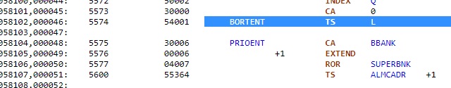 So, now, the execution resumes from the label BORTENT. The first instruction of this procedure, "TS L", puts the contents of the accumulator into the register L; the accumulator still contains the return address of the procedure BAILOUT. |
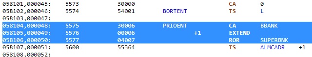 The instruction "CA BBANK" puts the contents of the variable BBANK into the accumulator. The couple of instructions "EXTEND" and "ROR SUPERBNK" makes an OR of the accumulator (which currently contains the variable BBANK) with an I/O variable SUPERBNK. What to do with? |
 The instruction "TS ALMCADR" put the contents of the accumulator into the variable "ALMCADR". Remember, this variable had already been initialized with another value (the return address of the procedure BAILOUT), and it has not been used meanwhile, which means that the previous initialization was useless. |
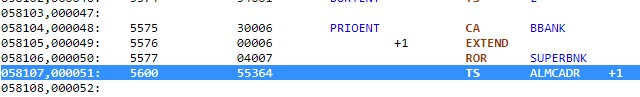
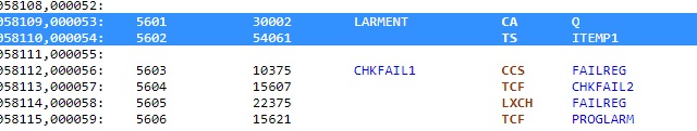 The instruction "CA Q" puts the contents of the register Q into the accumulator, and the instruction "TS ITEMP1" puts the contents of the accumulator into the variable ITEMP1. The register Q currently contains the return address of the procedure "BORTENT", so it means that the return address of BORTENT is put into the variable ITEMP1. |
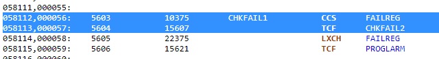 The instruction "CCS FAILREG" puts the decremented contents of FAILREG into the accumulator, but does not modify FAILREG; it tests the current contents of FAILREG, and skips the next instruction if it is null or less than zero. The next instruction "TCF CHKFAIL2" is executed if the current contents of FAILREG is greater than zero, and it jumps to the label CHKFAIL2. |
 The two next instructions "LXCH FAILREG" and "TCF PROGALARM" are executed only if the current contents of FAILREG was NULL. The instruction "LXCH FAILREG" exchanges the contents of FAILREG with the register L, which means that FAILREG is not NULL after this instruction, as the register L had a non null contents before the exchange (it was containing the return address of BAILOUT). The instruction "TCF PROGALARM" jumps to the label PROGALARM, which means that the next instruction is not executed after this instruction. |
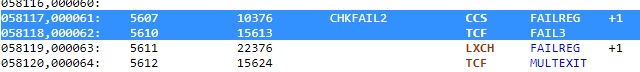 If we arrive on this label "CHKFAIL2", it means that the variable FAILREG was not greater than zero (otherwise the instruction "TCF PROGALARM" would have skipped it). The same test is made as at the label "CHKFAIL1", whith the same result. But, since we have arrived here because FAILREG was greater than zero, necessarily the next instruction "TCF FAIL3" will not be skipped, and this instruction jumps to the label FAIL3. |
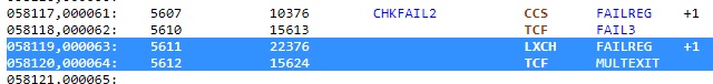 It also means that the two next instructions "LXCH FAILREG" and "TCF MULTEXIT" will never be executed, and so are totally useless. And the two previous instructions also are useless, for the next instruction has "FAIL3" as a label. |
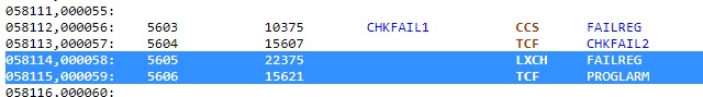
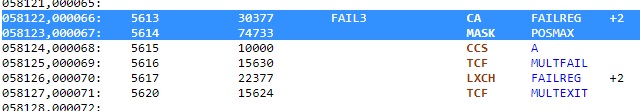 The instruction "CA FAILREG" puts the contents of FAILREG into the accumulator. FAILREG is currently not null, which means that the the accumulator is not null after this instruction. The instruction "MASK POSMAX" makes an AND of the accumulator with POSMAX; the name POSMAX lets suggest that it contains all ones, in which case it would left the accumulator unchanged, so still not null. |
 The instruction "CCS A" decrements the accumulator, but tests it before it was decremented. The next instruction "TCF MULTFAIL" is executed if the accumulator was greater than zero (before the instruction CCS), so it should logically be executed, it allows to jump tho the label MULTFAIL. |
 The two next instructions "LXCH FAILREG" and "TCF MULTEXIT" are only executed is the accumulator was null before the instruction" CCS", and should logically not be executed. The instruction "LXCH FAILREG" exchanges the contents of FAILREG with the register L. The previous instruction" LXCH FAILREG" has not been executed if we arrive here, for an instruction "TCF PROGALARM" follows the previous instruction "LXCH FAILREG", and PROGALARM is after this new instruction "LXCH FAILREG". It means that the register L still contains the return address of BAILOUT, and FAILREG is thus not null after this instruction. |
 The instruction "CS DSPTAB" puts the negative contents of DSPTAB into the accumulator, the instruction "MASK OCT40400" makes an AND of the accumulator with a variable OCT40400, and the instruction "ADS DSPTAB" adds the contents of DSPTAB to the acculumator. Note that, since the variable DSPTAB is used twice in these three instructions, it would have been possible to do it with only two instructions, using DSPTAB only once. |
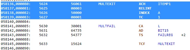 We now arrive at the label "MULTEXIT". The instruction "XCH ITEMP1" exchanges the contents of the variable ITEMP1 with the accumulator. Remember that the return address of the procedure BORTENT had been previously put into ITEMP1. So, it means that the accumulator now contains the return address of BORTENT. The instruction "RELINT" allows again the interrupts which had been inhibited at the beginning of BAILOUT. The instruction "INDEX A" makes that the accumulator is added to the operand of the next instruction. It means that the next instruction "TC 1" calls the address corresponding to the contents of the accumulator plus one, so the return address of BORTENT plus one, as the accumulator currently contains the return address of BORTENT. It means that the next instruction which will be executed after this instruction will be the instruction which is just after the instruction follows the call to BORTENT. Notice that this instruction should have been a "TCF" (jump), and not a "TC" (call) as there will be no return after this instruction. |
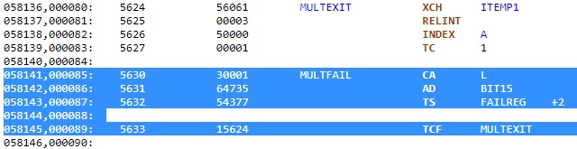 There can also be a jump to the label MULTFAIL. The instruction CA L" puts the contents of the register L into the accumulator, the instruction "AD BIT15" add BIT15 to the accumulator; the name of BIT15 suggests that it has its bit 15 at 1, so the accumulator contains now a non null value; the instruction "TS FAILREG" puts the contents of the accumulator into FAILREG. Finally the instruction "TCF MULTEXIT" makes a jump to the label "MULTEXIT", which makes an exit of BORTENT, so what's the use of changing again FAILREG as it will no more be used in the procedure BORTENT? |
 The two last instructions of MULTEXIT call the address of the instruction which follows the instruction which is just after the call to BORTENT (TC BORTENT). it means that the instruction which just follows "TC BORTENT" will never be executed. This instruction "OCT 40400" is not even an instruction, since it is just a value and not an instruction, so it is normal that it is not executed. But, in that case, why not just suppress it, and make directly a return to the instruction following "TC BORTENT", which could have been made with the couple of instructions "INDEX A" and "CAF 0" at the end of MULTEXIT? This would have spared one useless instruction. And, still better, the couple of instructions "INDEX A" and "CAF 0" could have been more efficiently replaced with the unique instruction "RETURN" which makes a return to the address contained in the register Q (into which the return address of BORTENT is put when BORTENT is called). So still a waste of instructions for a couple of instructions could have been replaced with a single instruction. In total, that makes two useless instructions. And the first instruction which is executed after the return from BORTENT is the instruction "INHINT" which inhibits the instructions again, which had been allowed just before returning from BORTENT. So, why allow interrupts if it is to inhibit them again immediately after? |
 The couple of instructions "CA TWO"and "ADD Z" add the contents of the program counter (that is the address of the next instruction, so the address of "TS BRUPT") to a variable TWO, which, like its name shows, contains the value 2, and puts the result into the accumulator; if other words, it is the address of "TS BRUPT" plus 2 which is put into the accumulator, and it corresponds to the address of the instruction "TC POSTJUMP", the instruction which is two words after "TS BRUPT"; to conclude, it is the address of "TC POSTJUMP", just after the instruction "RESUME", which is put into the accumulator; the instruction "TS BRUPT" puts the accumulator into the register BRUPT. The instruction "RESUME" allows to return from the interrupt, and first executes the instruction which is stored into BRUPT. But BRUPT does not contain an instruction, but an address, and an address cannot be executed as an instruction. As there is a return from interrupt, the processing stops here, and what has been processed makes no sense! |
 This procedure makes in fact absolutely nothing relevant, it is just here for the show. |
 And why would the engineers have cared to write a relevant program for a computer of which the memory was not even working? |
 Anyway, that does not mean that the astronauts were doomed when descending on the moon, for they still could jump in parachute before the lunar module was crashing on the moon. There is a very efficient lunar red cross on the moon, which is able to greet them and take care of them when they land on the moon. |

