
 This video deals about the anomalies report of the Apollo 12 mission report. This anomalies report is full of surprises I am going to present you with. Link to the Apollo 12 mission report which contains its anomalies report |
 1.1) Intermittent display and Keyboard Assembly 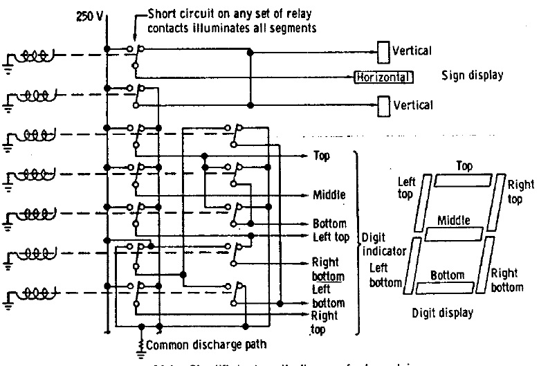 They say: "The crew reported several intermittent, all "8's" displays on the main display and keyboard assembly approximately 1-1/2 hours before launch, but no display malfunction occurred in flight." They also say: "The normally closed contacts of all relays are tied together; consequently, a short across the contacts of any one relay will apply the the voltage to all segments of each display". And they give this schema for the relay matrix of the display. In fact it is not true that the closed contacts of all relays are tied together, there is one which makes exception.  Now, let's suppose that there is a short between the contacts of a sign digit. The current can go through its contacts and follows all the paths I have colored, illuminating all the segments, save the bottom one, and the bottom left one. And what we see appear is what looks like a letter q, and not an eight. So, it is not intermittent all "8's" displays that the astronauts should have seen, but all "q's" displays! |
1.2 Hydrogen Tank Leakage 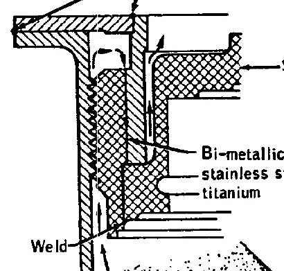 They complain about a leak in the hydrogen tank, and they explain that it comes from the imperfect junction between different metals. Two different metals are used in this tank, steel and titanium; but, as these metals are incompatible and cannot be welded, they use a bimetallic joint which allows to make the seal between the two metals. However, this joint would not allow to make a perfect seal, and there would be a leak through it, of which they show the path with arrows. 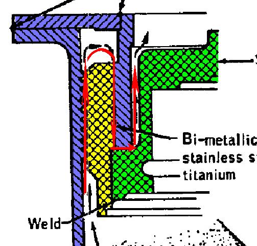 I have colored with different colors the different metals (titanium in blue, steel in green, and the bimetallic joint in yellow), and I show in red the path of the leak, according to the NASA engineers. 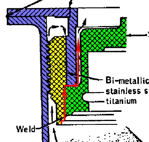 Oh really? Wouldn't there be a more direct path for the leak, that I show in red on this new schema?  It seems that the NASA engineers are afraid of simple explanations, and prefer more complicated ones! |
1.3) Electrical Potential Discharges 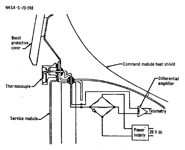 They say that there were two lightning discharges during the first minute of flight. The first one caused the loss of nine measurements (of which an outer suface temperature sensor, of which the shema is shown here). 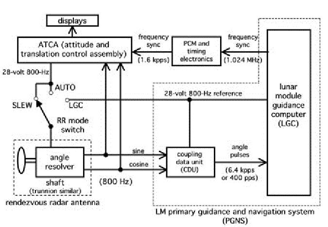 The second one would have caused the loss of reference of the inertial platform. According to the NASA engineers, it would have "set the high-order bits in the coupling display unit by the discharge transients introduced between signal ground and structural ground". This is a fancy explanation, for the CDU provides angle pulses to the LGC, and not direct angles, so it could not have set the high order bits of the angles; at worse some pulses would have been lost, and so it would not have caused a total loss of reference of the inertial platform. |
1.4) Open Stabilization and Control System Circuit Breaker 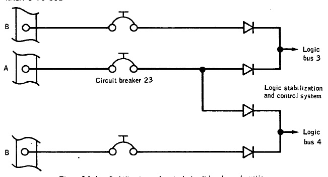 They say: "During systems checks after earth orbit insertion, circuit breaker 23 for stabilization and control logic bus 3 and 4 on panel 8 was found in the open position". A crewman closed the circuit breaker, and it remained close for the rest of the mission. In fact they concluded that this circuit breaker was probably not set during prelaunch, because this circuit breaker is not specifically verified to be in the proper position at prelaunch checking"!  The people in charge of the checking were probably busy playing cards rather than making the necessary verifications! |
1.6) S-band Signal Strength Variations  They say: "Operation of the S-band high gain antenna in the narrow beam mode resulted in a decrease of approximately 10 to 12 dB in both uplink and downlink signal strength on several occasions." 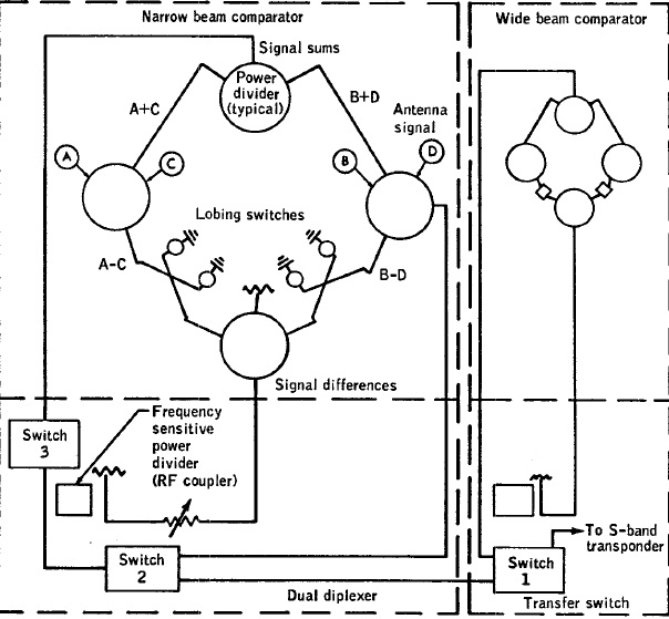 The signals received by the dishes are compared in order to determine the direction of the signal transmitted from earth, and this comparison allows to automatically orient the antenna toward the direction of the signal. When there is a loss of power in the signal, it would come from a temperature sensitive circuit connection which would make that the the signal received on one dish would be dephased of 180�; this would create a shift of 5�, and a loss of gain of more than 10 db. It would be the exposition to the sun which would create an overheat causing this malfunction. But the exposition to the sun is not very different along the revolutions; a revolution is indeed around two hours long, and the lunar day is almost one month long. So, why so much difference in the diagrams of the gain? 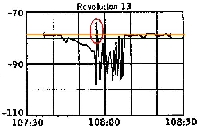 Furthermore, on the diagram of Revolution 13, in the part of the diagram on which the gain shows brutal drops, there is a peak which goes above the optimal value of the gain; how is it possible, how can the gain be better than optimal?  The fact that the signal could lose more than 10 db was sometimes forcing the astronauts to switch the antenna to manual. (on my animation I am exaggerating the oscillation of the antenna, this ocillation is only for an illustrative purpose, only to show that it is stronger than normal).  Now, if the dish which causes the problem (i.e. which is connected to the failing temperature sensitive connection) is eliminated from the signal comparison, the shift is consistently reduced from 5 degrees to 1 degree, and the loss of gain becomes only 1.5 db instead of more than 10 db if the failing dish is kept in the signal comparison. (the oscillation I show on this animation does not exactly reflect the reality, only purposed to show the important difference between the failing dish kept in the signal comparison, and this one eliminated).  I show here with a red line a loss of gain of 1.5 db relatively to the optimal gain in the different diagrams of the gain when there was a loss of gain because of a failing temperature sensitive connection causing the dephasing of the signal from a dish. And we can see that, if the failing dish was eliminated from the signal comparison, it would allow to have a quite good reception of the signal, perfectly acceptable. So, why not allow the astronauts to eliminate a failing dish in case that this problem occurs, rather than switching to manual? Here the problem was intermittent, but imagine the problem would have become permanent instead of only being intermittent? It would have forced the astronauts to remain on manual when they wanted to have good communications with the earth. If the astronauts had the possibility of just eliminating the failing dish in the signal comparison, it would allow them to keep the automatic angle pointing mode, and have acceptable communications with the earth, without caring about reorienting the antenna toward the earth themselves. |
1.7) Discrepancy in indicated oxygen usage 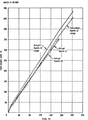 They say: "At the end of the mission there was a discrepancy of approximately 27 pounds of oxygen between the measured total cryogenic oxygen usage and the calculated combined environmental control system and fuel cell oxygen usage". The problem is that the calculated oxygen usage includes the oxygen losses during urine dump operations, which, according to the NASA engineers themselves, can only be estimated. So, how can they know if this discrepancy would not just come from a bad estimation of the oxygen losses during urine dump operations, which would have been underestimated? |
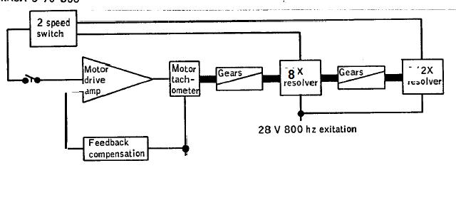
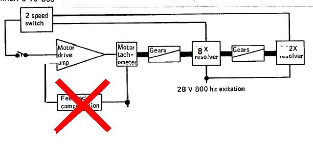
1.9) Zero Optics Mode fluctuations 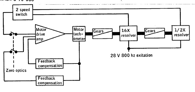 They say: "The computer register which contains the angular position of the optics shaft was observed to fluctuate as much as 0.7 degree when the system was placed in the zero optics mode. The crew reported that the shaft mechanical readout on the optics also reflected the fluctuation". In fact this interface is illogical for several reasons. |
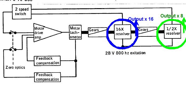 First we see that the output of the tachometer is first multiplied by 16 (in frequency), and then divided by 2, giving a tachometer signal multiplied by 8. |
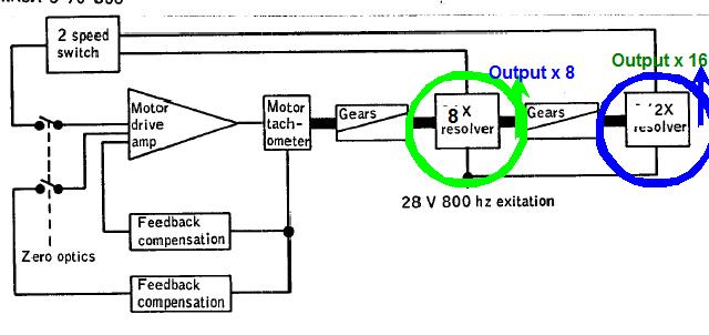 This is illogical: It would be simpler to first multiply the tachometer signal by 8, and then to multiply it by 2, to obtain a tachometer signal multiplied by 16; we would obtain the two same signals (in reverse order), but in a simpler way, using less electronics. |
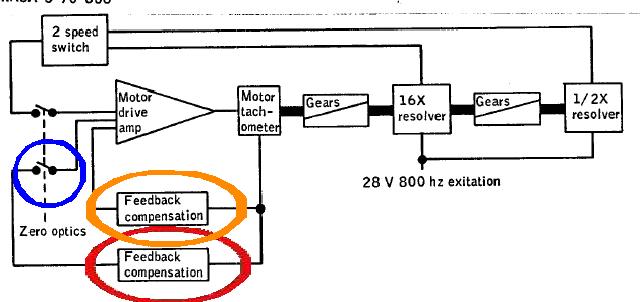 Then there is a feedback compensation which is permanently applied, but there is also another one which is applied in case that the zero optics switch is closed; the second one is useless, as there already is the first one. |
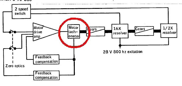 The motor drive amp output comes into a tachometer (circled in red). But what is a tachometer? |
 A tachometer is a device which allows to generate pulses from the rotation of a wheel. Its resolution is characterized by the number of pulses generated per full rotation of the wheel. It allows to measure the rotation of the wheel by counting the number of generated pulses. |
 It also allows to measure the speed of a spinning wheel; the faster the frequency of the generated pulses, and the faster the rotation of the wheel. It is used to measure the speed of cars, since the rotation speed of the wheels is related with the speed of the car. |
 It also allows to follow the displacement of a conveyor; to know how much a conveyor is moved, the number of generated pulses read is multiplied by the circumference of the tachometer wheel, and divided by the number of pulses per full rotation of the wheel, to finally obtain the distance that the conveyor has moved. |
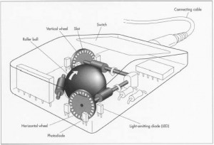 This principle is also used in mechanical mouses. As you move the mouse, a spherical ball turns which makes turn two wheels disposed perpendicularly, which each send pulses to an electronic circuitry as they turn, which are counted or decounted to update the position in the two directions that the mouse moves. |
 This is how the computer can know how you move the mouse and update the position of the mouse cursor on the screen. |
 If we correct the interface to eliminate all the anomalies which have been show, we obtain this: - The signal is first multiplied by 8, and then by 2, to obtain the two multiplied signals. - The multiplied signals are inputted into the speed switch block, without applying a sine transform to one of the signals, and only one output comes out of this block. - The redundant feedback compensation is suppressed. But, if this new interface is more logical than the original one, it does not mean that it is correct for as much. |
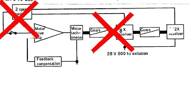 First the zero optics cannot be obtained just by looping the multiplied signals on the motor drive amp. Indeed what does that mean making the zero on the optical system? It means that, when the optical system is centered, the system must be warned that it must take it as a reference, and count or decount pulses from this reference. It certainly cannot be achieved just by looping the multiplied tacho signals. So, the multiply blocks of the tacho signal are useless, and their output signals must not be looped back on the motor drive amp. |
 Then what does mean the feedback compensation, and when is it used? The feedback compensation is used when the command must produce a desired effect, and the produced effect can be measured; the desired effect and the measured effect are then differentiated and the difference is used to correct the command till the measured effect matches the desired effect. |
 But, in the case of the optical system, the motor drive amp does not produce a command, but just allows to generate pulses, via the tachometer, which are counted to measure the displacements of the optical system. So, there is no point using a feedback compensation in this context. |
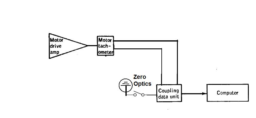 So, finally, after having eliminated the useless parts which should not be there, we obtain this final interface: - The tachometer generates pulses on two signals, of which the phase difference allows to know in which direction the motor wheel is turning (so to know if the pulses must be counted or decounted); these two signals are inputted into the CDU which counts (or decounts them); the computer can read the count via an I/O instruction. - A zero switch (or pushbutton) is connected to the CDU; when this switch is set, it sends a signal to the CDU which allows to clear the pulse counter of the CDU, so that, when the computer reads zero on the counter, it knows the optical system is currently centered. Now we have a coherent optical interface. |
1.10) Clogged Urine filters 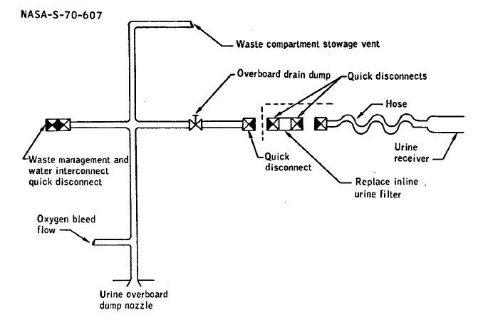 They say: "By about 215 hours, the crew reported that both urine filters had clogged and that the urine overboard dump system was being operated without a filter. ..The filter was then replaced by a spare unit which also clogged 2 days later. The urine dumping system operated satisfactorily without a filter for the remainder of the mission (approximately 30 hours )." They also say: "Postflight test of both filters indicated that the clogging was primarily due to urine solids... An analysis of the flushing water residue revealed urine solids and a small trace of lubricant but no lunar material." It means that the test of the urine dump system could have been done on earth, and that, very obviously, it had been unsufficiently tested before the mission, if tested at all! They say they made improvements of this dump system in the next missions, but why didn't they make them before! It's probably because the engineers in charge of the tests for Apollo 12 were too busy playing cards! |
1.11) Window contamination 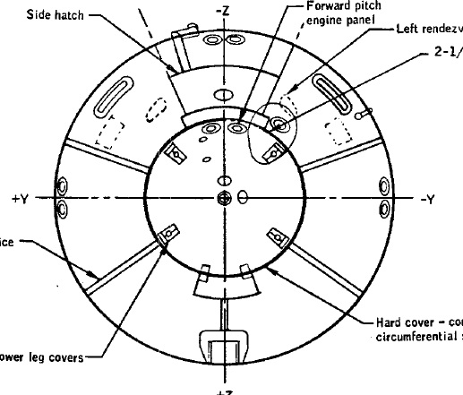 They say: "The hatch, left-hand side, and both rendezvous windows of the command module had considerable amounts of contamination appearing as vertical streaks on the exterior surfaces,". They also say: "A procedure requires that these gaps be sealed with a composition sealant on final installation of the boost protective cover; however, some gaps were not sealed." The level of unprofessionalism in the construction of the command module is just astounding! 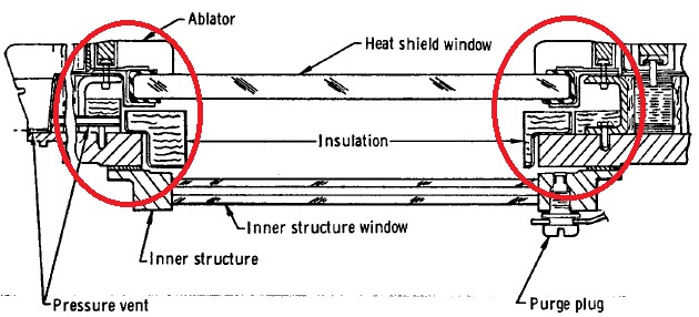 They also say: "This contamination could have resulted from either entrapped moisture in the hatch area between the heat shield and the pressure structure or from out- - gassing of sealant materials in this area". Now, look at this cross section of hatch window: why is there a such asymmetry in its conception? |
1.12) Improper deployment of VHF Recovery Antenna 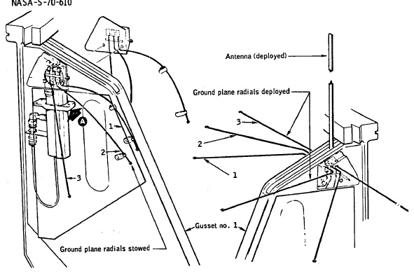 They say: "During the command module descent on the main parachutes, ground plane radials 1 and 3 of VHF recovery antenna 2 did not properly deploy. However, voice communications with the recovery forces while using this antenna were not significantly affected." The voice is transported on a high frequency carrier, so, if the voice of the astronauts could be received by the recovery forces, without significant degradation, so could its carrier and any other signal this carrier could transport. They also say: "For Apollo 13 and subsequent missions, recovery antenna 2 will be used for recovery beacon transmissions instead of voice." This phrase would mean that the signal transmitted by Antenna 2 could carry either recovery beacon transmissions or voice, but not both; in reality, it can carry both. Finally they say that they made improvements for the proper deployment of the radials in the next missions, but couldn't they have made these improvements before, or were they so much lacking imagination that they could not see that there could be problems in the proper deployment of the radials in the conditions of the missions preceding Apollo 13 (notably a cloth flap which was supposed to prevent entanglement with the parachutes, and which would have stuck to the radials). Now, don't underestimate the engineers in charge of the tests for Apollo 12. if they didn't study a solution for the proper deployment of the antenna radials, it's only because they were too busy playing cards! |
1.13) Command Module Reaction Control Isolation Valve Failure 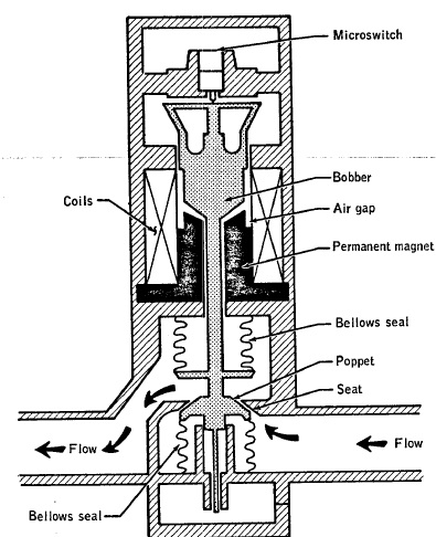 They say that the bellows which keep an isolation valve closed would be damaged when the valve is closed at activation or purging. So, they urge the future crews to care about having the valves open prior to system activation and purging. Oh really, the crews have to care about that? Couldn't the valves be automatically opened each time there is a system activation or purging, or is it beyond the capacity of the NASA engineers to do it automatically? No, it was not beyond their ability, but they had to choose between devising a system to automatically open the valves at system activation or purging and playing cards...and they chose to play cards! |
1.14) Oxygen Hose Retention Bracket Failure 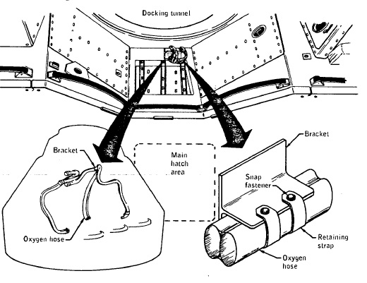 They say: "At earth landing, an aluminium retention bracket for the oxygen hoses pulled loose from the main display panel". And: "Postflight inspection of the bracket revealed an inadequate adhesion area between the bracket and the panel. The adhesive material was not uniformly spread under the bracket, thereby creating large voids". But this problem has been solved in the next missions: "Manufacturing requirements have been changed to include torque testing of the bracket to assure that a proper bond has been achieved." What did they do when they tested the material for Apollo 12? Answer: They played cards! |
1.16) Severed Lanyard On Forward Heat Shield Electrical Leads 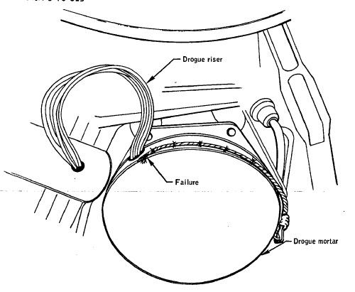 They say: "During postflight inspection of the upper deck, the lanyard which retains the forward heat shield electrical cable had been severed, and only 18 inches of the approximately 45-inch lanyard remained." Imagine the same thing had happened to the parachute cords! |
1.17.a) Shift in Quad D Helium Manifold Pressure 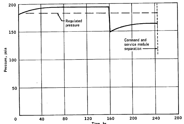 They say: "The measurement for reaction control quad D helium pressure indicated erroneous values throughout the flight. During the first 70 hours, the pressure exhibited a slow drift of about 14 psia upward. At approximately 160 hours, the measurement then shifted from 192 to 150 psia, followed by a second slow drift upward". Then they say: "Both the slow drifts upward and the Jump shown on the figure tend to support the conclusion that the strain-gage bonding had weakened." The fact that the strain-gage bonding had weakened only explains the shift down of the pressure, not the slow drifts upward. If the shift down of the pressure had happened while the pressure was still slowly drifting upward, the pressure would have gone on drifting upward after it shifted down because of the weakening of the strain-gage bonding. But the brutal shift down occurred after the pressure had stabilized, not while it was slowly drifting upward... 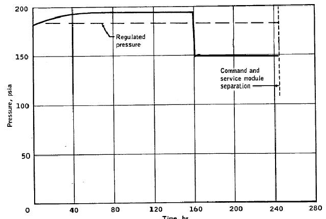 ...So, there should have been no drift upward after the shift down due to the weakening of the strain-gage bonding, and the indicated pressure should have looked like shown on this diagram. |
1.17.b) Low Readings From Suit Transducer 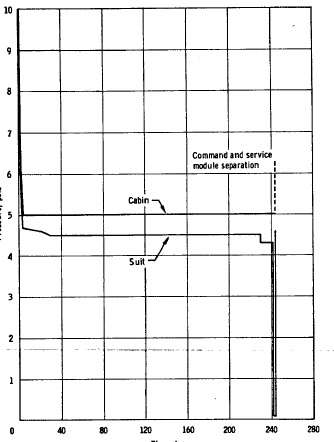 They say that the suit pressure transducer indicated less than the expected pressure throughout the mission, and the differential of pressure varied, was more or less important. Postflight tests indicated internal contamination from metallic nickel-plating particles which would cause an irregular transducer output. This failure was considered an isolated occurence for Apollo 12 (perhaps to punish the engineers for playing cards insteads of making serious tests) , and therefore no modification was made to prevent this from happening in future missions (therefore the same problem could have repeated in other missions). |
1.17.c) Erratic Potable Water Quantity They say: "Potable water quantity data were erratica prior to launch and also occasionally during flight. Operation of this sensor was not necessary because the known onboard water quantities were within launch specifications. Therefore, replacement, which would have required rescheduling the launch, was not performed." In other words, they did not care about solving the problem of the sensor (due to corrosion), because they knew that the water quantities were normal, and sufficient for the mission. But it also means that the astronauts could not know what was exactly the remaining quantity of water during the mission, which was essential for them to make a rational use of water.  It's like you had a flask of water in the desert, and could not refill it before having reached a refill point; if you are able to see how much water is left in the flask, you can organize your consumption of water to make it last till the refill point; but suppose you are not able to see how much water is left in the flask? You would start to stress and constantly worry about the unknown remaining level in the flask! |
1.17.d) Fuel Cell 3 Regulated Hydrogen Pressure Decay They say: "The fuel cell 3 regulated hydrogen pressure gradually decayed from 61.5 psia to about 59.5 psla, but remained within specification limits". And: "The apparent pressure drop has been attributed to a pressure transducer failure, with the most probable failure mode being a small leak through or around the stainless steel diaphragm in the transducer". This is something they could perfecly have detected before the mission if they had made serious tests. But they had the choice between making serious tests and playing cards...and you know what they chose! |
1.18) Intermittent Tuning Fork Display 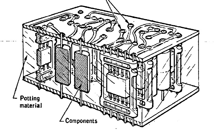 They say: "The tuning fork display on the panel 2 mission clock operated intermittently prior to and during launch." And: "Operation of the tuning fork indicates the mission clock has switched from the central-timing-equipment timing signal to an internal timing source, thus indicating loss of the central timing signal." The reason they give for this is: "Based on previous mission clock failures, the most probable cause for this anomaly is a cracked solder Joint in the cordwood construction.". So, they are not even able to guarantee a correct working of the mission clock, and they want to go to the moon! In the next missions they designed a new clock design which was eliminating the cordwood construction and was less susceptible to electromagnetic interference. Oh, couldn't they have done it before, did they need to land on the moon before doing it? Yes, they needed, otherwise the engineers in charge of the tests whould have had to make tests instead of playing cards! |
1.19) Unacceptable VHF communications 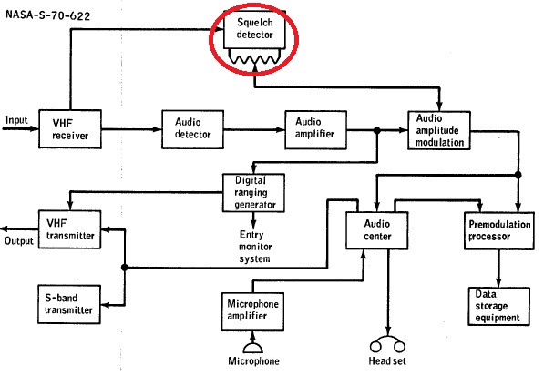 They report two different problems about VHF communications. First, they had a squelch system which was cutting the communication each time that it was falling under a given level supposed to be only blank, with no communication from the ground. 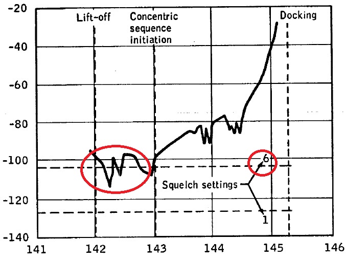 The problem is that, when the squelch was set on the maximum level (6), it was possible that, at times, the communication level could fall under the squelch setting, even though it was not a silence, and the operator was currently talking; it that case, the astronauts could lose a part of what the operator was saying, because the squelch system was unduly cutting the communication. 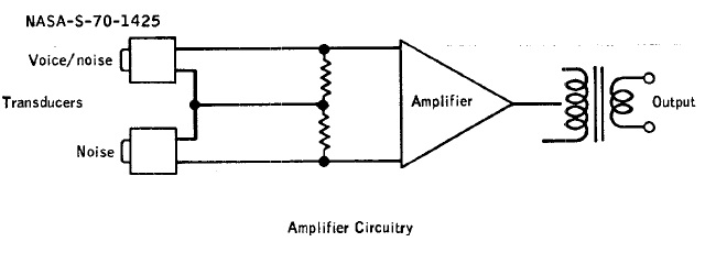 A second problem is that the NASA engineers had devised a system which was allowing to remove the noise from the voice when the astronaut was talking in the microphone. 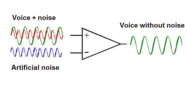 The principle was that a pure noise was generated and subtracted from the "Voice+Noise" signal, thus removing the noise from the "Voice+Noise" signal and allowing to obtain a pure voice, not polluted by noise.  The problem is that, when the headset was not properly adjusted, the level of the signal "Voice+Noise" could not be what expected, and the pure noise, instead of just removing the noise in the signal "Voice+Noise", was also removing a part of the voice, thus altering the voice. So, they were recommending the astronauts to well adjust their headset, so this would not happen, and the noise could be correctly removed by this system without altering the voice. But this is completely ridiculous. In my schema, I have simplified the voice by representing it as a single wave, and also the noise.  In reality the voice is made with plenty of waves of different frequencies and amplitudes called harmonics. Voice synthesis works by creating these harmonics and adjusting the amplitude of the different harmonics. The noise is also made with different waves of different frequencies and amplitudes, and these frequencies and amplitudes are all random. It means that it is completely illusory to try to reconstitute the noise which is mixed with the voice; the reconstituted noise will never match a noise of which the harmonics have not only random frequencies and amplitudes, but also varying ones. Even if the headset is perfectly adjusted, this system will degrade the voice without removing the noise which goes with (and even increasing this noise). |
2.1) Docking Hatch flood  They say: "The floodlight is controlled by a switch that is actuated by opening and closing the docking hatch in a manner similar to that for a refrigerator door. The crew checked the operation of the hatch switch and verified floodlight operation by manually depressing the plunger. However, the hatch did not. depress the plunger sufficiently to actuate the switch." In other words, the docking hatch works less well than your refrigerator door! They solved this problem in the next missions, but once again, they failed to make serious tests for Apollo 12. Even refrigerator makers make more serious tests than the NASA engineers. But don't be too hard on the NASA engineers, it's only because they were playing cards! |
2.2) Water in the Suit Loop  They say: "After the first extravehicular activity, the Commander reported that his boots had water in them and that the suit inlet hose was delivering cold moist air when disconnected. The Lunar Module Pilot also noted drops of water in his inlet hose." They also say: "Prior to the sleep period, the water was drying in the Commander's suit". Water dries when exposed to air; how could the water dry in the suit, without being exposed to air? And both astronauts of Apollo 12 reported the problem, so it would be surprising that the problem didn't also occur in Apollo 11.  They say: "For Apollo 13 and subsequent missions, a flow limiter will be added to the primary lithium hydroxide canister to reduce suit- loop gas flow and consequently limit the separator speed to within the no-splash range". So, they waited for Apollo 13 to solve the problem. The conclusion is that they did no serious test of the suit before Apollo 12. How could they if they were playing cards? |
2.3) Carbon Dioxide Sensor Malfunction  They say: "Following lunar lift-off, the crew reported a master alarm at about the time of ascent-engine shutdown. Ground data show a short-duration spike in the indicated carbon dioxide partial pressure at that time." They explain the problem this way: "The carbon dioxide sensor is sensitive to free water, and the malfunction was probably caused either by water from the water separator sump tank entering the sensor or by water bypassing the water separator and entering the sensor." They finally say: "This vent line has been rerouted for Apollo 13 and subsequent vehicles." So, they waited for the problem to occur before rerouting this vent line, which yet seemed an obvious thing to do! Don't think that it was beyond the capacity of the engineers of Apollo 12 to do it, but playing cards is so enthralling! |
2.4) Tracking Light Failure  They say: "At the beginning of the second darkness pass after lunar lift-off, li the crew reported that the tracking light had failed. Subsequent cycling of the light switch indicated that power consumption was normal, indicating the high-voltage section of the light had experienced a corona failure." This is the reason they give for this problem: "Tests indicate that off-axis solar impingement on the flash head reflector can cause temperatures on the flash head potting as great as 500 � F, which could degrade the potting compound enough to cause a corona." And finally they explain how they solved the problem for Apollo 13 and subsequent missions: "For Apollo 13 and subsequent missions, the tracking light will be redesigned to reduce the 4000-volt voltage source to 2000 volts, and flash head potting will be protected from direct solar impingement." And how about making these modifications in time? Was Apollo 12 really a lunar mission or a simple flight test? The Apollo 12 engineers knew that Apollo 12 was a serious mission, but playing cards is also very serious! |
2.5) Equipment Compartment Handle did not release 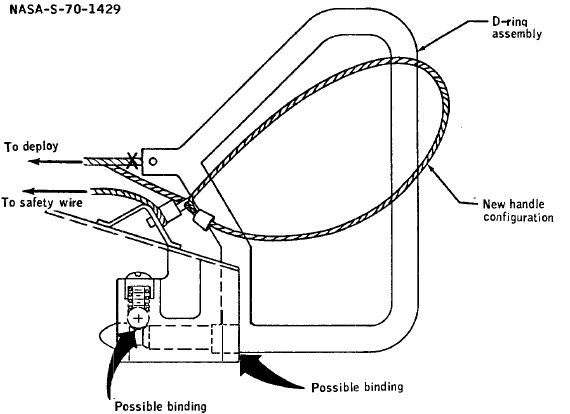 They say: "During the initial egress, the modularized equipment stowage assembly was to be deployed by pulling a special D-ring handle. Although the Commander was unable to release the handle from the support bracket, it could be rotated in its bracket." What they did to solve the problem in the next missions: "For Apollo 13 and subsequent, the D-ring will be deleted and a loop will be clamped to the end of the deployment cable. The loop will be retained using the same type of pin presently installed to retain the safety wire." But they could not have done this modification before Apollo 12? no they could not! The Equipment Compartment Handle could only be tested on the moon, it could not be tested on earth, could it? Especially when those who were in charge of the tests were playing cards instead! |
2.6) Torn Forward Hatch Themal Shield  They say: "During egress, the Commander's portable life support system came in contact with and tore the hatch micrometeoroid shield. Such a tear could represent a potential hazard to the suit." But they solved this problem in the next missions: "For Apollo 13 and subsequent, the thermal shield thickness will generally be increased from 0.0020 to 0.040 inch. In addition, the diameter of the shield mounting holes will be increased from 0.375 to 0.5 inch" And how can these modifications prevent the PLSS from coming in contact and tear the hatch micrometeoroid shield? How about widening the hatch to prevent the PLSS of the astronaut from coming in contact with the hatch? |
2.7) Early Illumination of the Low Level Descent Light 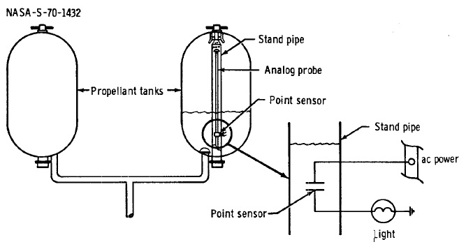 They say: "The low-level light for descent propulsion propellant quantities illuminated about 25 seconds early. The low-level light is activated and remains latched on when any one of the four low-level point sensors is uncovered." 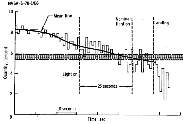 This diagram explains why the the low-level light illuminated too early: This is because the reading of the remaining propellant quantity was too imprecise and varied too much; at one moment this reading fell under the level causing the illumination of the low-level light, though the remaining quantity was still above the level causing the illumination of this light. In fact, if the reading of the level was so imprecise, it was because it was unsufficiently sampled, only one sample per second. Increasing the frequency of the sampling allows to have a better, more precise reading of the remaining propellant quantity. On Apollo 13, they increased the frequency of acquisition from one sample per second to 100 samples per second, which allowed to have a more accurate reading of the remaining propellant quantity, and avoid to illuminate the low-level light too early. Any decent engineer would know that a too low sampling frequency gives a bad uncertain measure, and that, the higher the sampling frequency, and the better the measure. Do I mean that the NASA engineers were not decent? Oh no, I know they were very decent, but I also know that playing cards was more important for them than making serious tests for the lunar mission! |
3.1) Color Television Failure 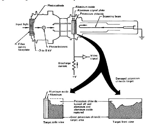 The camera would have had its target partially damaged by the sun.  The part of the image corresponding to the damaged area of the target was appearing mostly white; it could have been expected that the part correponding to the undamaged area of the target could have recorded something normal, but instead it was appearing completely black, and the cause of this was identified as the automatic light-level control; if the automatic light-level control was disconnected, the undamaged area of the target could record an image. 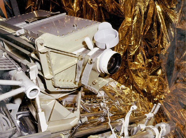 Then the NASA engineers have devised an absolutely revolutionary system that they of course patented: Equip the cameras with a cap that the astronauts could place on the lens to protect it from the sun when they were transporting it. Another improvement was the use of an image sensor which was less susceptible to damage from intense light levels. And they could not have used a such sensor for Apollo 12? Was this image sensor invented between Apollo 12 and Apollo 13? No, but replacing the image sensor would have meant interrupting a exciting game of cards, and this was out of question! |
3.2) Intermittent 16-mm Camera During Ascent 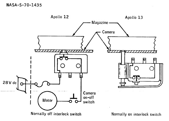 They say: "The 16-mm camera was turned on Just before lift-off, but it stopped after a brief period of operation. During ascent, it was activated two additional times, and each time it stopped after 20 or 30 seconds of operation. During rendezvous, the camera was operated by constantly depressing the triggering button, hereby overriding the automatic shutoff." They explain it this way: "the characteristic sensitivity of the magazine interlock microswitch installation is such that the operating limits of the switch could cause intermittent actuation." They solved the problem in the subsequent missions: "The problem will be resolved by changing the interlock switch to a configuration that is much less sensitive to variation in switch settings." Oh really, and they could not have tested it before? Oh I was forgetting, they were playing cards! |
3.3) Difficulty in Removing the Radioisotope Fuel Capsule 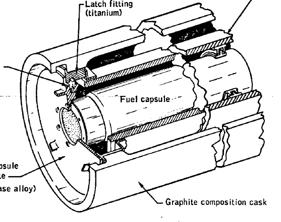 They say: "The crew experienced difficulty in removing the radioisotope fuel capsule from the fuel cask assembly during deployment of the Apollo lunar surface experiments package." For Apollo 13, they solved the problem: "The outside diameter of the 0.10-inch long contact surface, while remaining within design limits, may be reduced as much as 0.005 inch for ease of capsule extraction. All existing capsule backplates will be reworked in this manner." For Apollo 12, they couldn't, for they were playing cards, less boring than testing a Radioisotope Fuel Capsule. |
3.4) Difficulty in deploying the Passive Seismometer 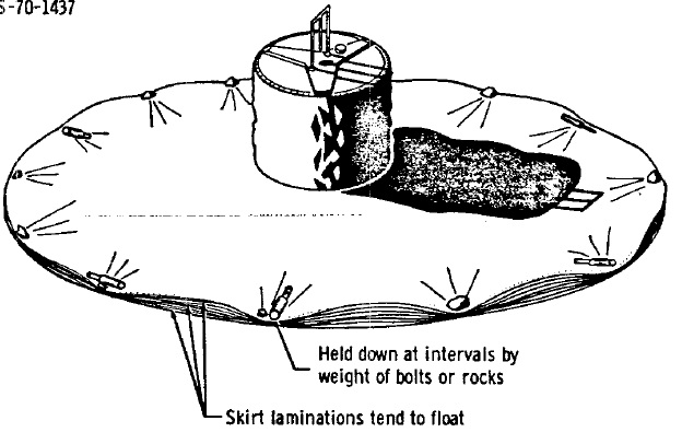 The astronauts had difficulty at applying the thermal shroud on the lunar surface, which one tended to delaminate and rise up off the lunar surface. They first tried to put lunar soil on the periphery of the shroud, but it did not work; so finally that had the idea to put bolts removed from the pallet during deployment, and, this time, it worked. For Apollo 13 and subsequent missions, they'll sew weights on the periphery of the shroud to make it stick to the lunar surface. About thinking to make it before Apollo 12, don't even think about it: They were playing cards, and fuck the tests and improvements! |
3.5) Difficulty in Deploying the Cold Cathode Ion Gage 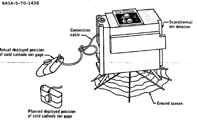 They say: "The cold cathode ion gage would not remain upright when deployed. Its final position was on its back with the sensor aperture at an angle of approximately 60 degrees from the horizontal but was satisfactory" They'll improve this problem on Apollo 14: "For Apollo 14 this equipment will be flown, and the wires of the connecting cable will be tied at 6-inch intervals instead of being wrapped with heavy Mylar tape." About making tests before Apollo 12? The NASA engineers will tell you: "The astronauts could make the tests themselves on the moon, we had more important things to do...like playing cards!" 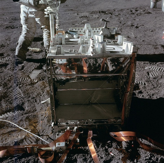 Anyway, when we see the junk that the ALSEP, improvements or not, that was not making a big difference! |
3.6) Unsatisfactory Tool Carrier Bag Retention 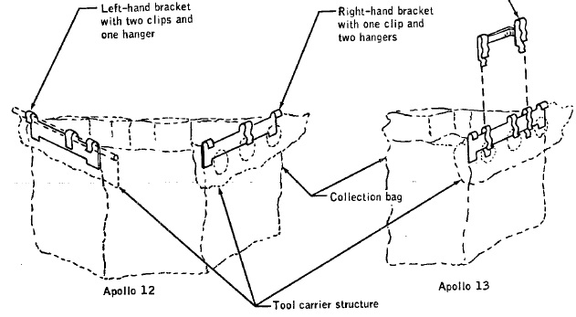 They say: "At the beginning of extravehicular activity, the empty tool carrier collection bag tended to rise out of the tool carrier until some lunar surface soil was put in to hold it down." Once again, a solution will be provided for the subsequent missions: "A separate double spring clip, which reaches over both the bag hanger and tool carrier structure, will be added for Apollo 13 to provide the necessary retention force as shown in the figure". And the NASA engineers in charge of the tests for Apollo 12 will tell you: "It's not us the testers, it's the astronauts, we only are here to play cards." |
3.7) Intermittent Counting on the Command Module 70mm Camera 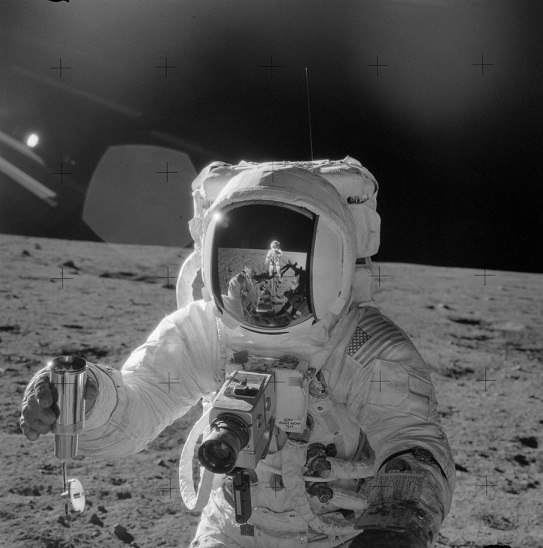 They say: "During landmark tracking using 70 mm camera with the 500 mm lens, the magazine opened up and the counter did not agree with the crew count. The crew had inadvertently actuated the mechanism which opens the magazine, allowing the entire film holder portion of the magazine to come out of the magazine housing."  Then the NASA engineers found an absolutely ingenuous idea to solve this problem, an idea which will remain in the annals of science: "Since there is no requirement to remove film during the mission, tape will be placed over the retracted film release knob after loading the magazine, and proper frame counting should be preserved." And, if the engineers in charge of the tests for Apollo 12 didn't think about it, it's only because they were playing cards! |
3.8) Suit Pressure Pulses  They say: "During the second extravehicular period, the Lunar Module Pilot indicated that he felt something which could have been two pressure pulses in the pressure garment assembly, but he could not determine whether the pulses were increases or decreases in pressure." The engineers found no evidence of a system malfunction, so they came with this explanation: "The crewman had a stuffy head condition during this time period. "Popping" the ears was ruled out, but some other effect internal to the ear may have created the sensation." My theory is that the pulses that the crewman felt would have been the beats of his own heart! On what is my theory based? On, this phrase: "The mission time for the reported pressure pulse, based on a sharp rise in the Lunar Module Pilot's heart rate, was determined to be between 133:09:00 and 133:12:00." |
3.9) Stoppage of the Lunar Surface Camera Counter  They say: "The exposure light on the lunar surface close-up camera came on for each exposure, but the mechanical exposure counter did not count every exposed frame. The counter is housed in the handle, which is a matte surface, uncoated aluminum casting. Postflight analysis has indicated that, during extravehicular activity, the camera reached a stabilized handle temperature of approximately 220 � F, which is above the mechanical interference point for the counter." And, once again the NASA engineers found an absolutely ingenuous idea to solve this problem, an idea which will also remain in the annals of science: Paint the handle of camera in white to reduce its temperature. And, if the engineers in charge of the tests for Apollo 12 did not think about it...it's only because they were playing cards! |
3.10) 70-mm Lunar Surface Camera Difficulties 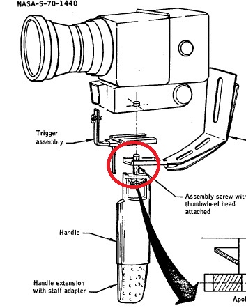 For both astronauts, the camera assembly became loose and needed retightening. They say: "In the process of retightening on the lunar surface, the thumbwheel fell off the Lunar Module Pilot's camera assembly, making reassembly impossible" 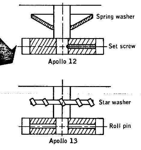 They found the solution for the subsequent missions: "For future missions, the cupped spring washer will be replaced by a star washer to resist rotation and loosening of the assembly screw, and the thumbwheel will be secured to the screw with a roll pin, instead of a setscrew." The engineers in charge of the tests for Apollo 12 could also have applied these solutions,...if they had not been so busy playing cards! |
3.11) Tone and Noise During Extravehicular Activity  They say: "An undesirable tone, accompanied by a random impulse noise signal, was present intermittently for the first l-l/2 hours of initial extravehicular activity. The same tone, but without the noise, was present for approximately 12 seconds during the second extravehicular period. This condition did not degrade voice communication but was annoying to the crewmen." In fact, an analysis of the tone power spectral density revealed that the peaks were corresponding with the frequency of the fan motor. The fan motor signal should normally have been filtered by the microphone amplifier regulator, but this regulator failed to eliminate this signal. They say: "The normal operating voltage for the microphone amplifier is from 15.7 to 20.5 volts. When the microphone amplifier supply voltage is above the regulator threshold of 12.5 volts, the tone interference does not enter the audio system." In short, they were not able to apply a correct voltage to the microphone amplifier. The engineers in charge of the test of Apollo 12 would probably have applied a correct voltage to the regulator, probably...if they had not been playing cards! |
3.12) Cracked Weight Bags  They say; "The weigh bags were apparently too brittle and therefore cracked and tore when handled on the lunar surface. Those stowed in the sample return container were used to hold the samples of lunar surface material for weighing, and those stowed in the equipment transfer bag were used as collection containers (tote bags) during the geology traverse." Thankfully, the solution existed and was applied from Apollo 13: "The Apollo 12 weigh bags were made from Teflon film. For Apollo 13, the collection containers will be made of a Teflon cloth, which is more flexible and is not as subject to cracks and tears." This solution could even have been applied in Apollo 12... if the engineers in charge of the tests had not been playing cards! But, if you knew that all the efforts you are doing would not allow a lunar module to land on the moon, wouldn't you play cards too? |
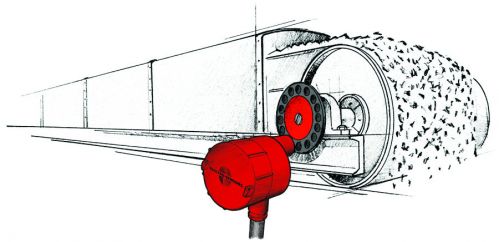
 This last part is about the use of the PLSS in Apollo 12. It is is based on a table in the mission report of Apollo 12, at page 8-20.  On this animation, I show the flow of oxygen inside the PLSS; it were automatic valves, electrically commanded, which were allowing to regulate the flow.  On this animation, I show the flow the water inside the PLSS; it also were automatic valves, electrically commanded, which were allowing to regulate the flow.  So, both for the oxygen and water, electrically commanded automatic valves were allowing to regulate the flow, which means that, the more the astronaut was consuming oxygen and water, and the more also he was using electrical power. This is an important precision for what follows. 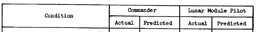 The table I have used contains two columns for each astronaut, one indicates the real use, and the other one the predicted use.  Now, let's examine the data of first EVA. 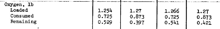 In first EVA,Conrad has used 0.725 pounds of oxygen, while he was predicted to use 0,873 pounds, so he used less than what was predicted. Al Bean has also used 0.725 pounds of oxygen, while he was also predicted to use 0.873 pounds, so he also used less than what was predicted. 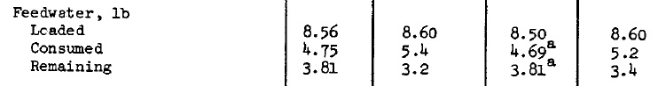 In first EVA, Conrad has used 4.75 pounds of feedwater, while he was predicted to use 5.4 pounds of it. And Al Bean has used 4.69 pounds of feed water, while he was predicted to use 5.2 pounds of it.  Finally, in first EVA, Conrad has used 187 watt-hour of electrical power, while he was predicted to use 130 watt-hour only, which is strange, for, as he used less oxygen and feedwater that what was predicted, he should also have used less electrical power than what was predicted. Al Bean has used 188 watt-hour, slightly more than Conrad, while he has used a little less feedwater.  Now, let's examine the data of second EVA, and that's where the fun begins. 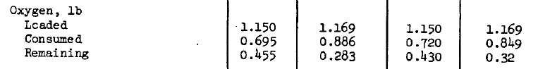 In second EVA, Conrad has used 0.695 pounds of oxygen, while he was predicted to used 0.886 pounds of it, and Al Bean has used 0.720 pounds of oxygen while he was predicted to use 0.849 pounds of it; notice that, while Al bean was predicted to use less oxygen than Conrad, he has instead used more of it. 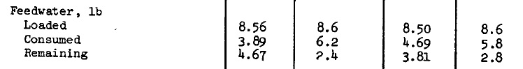 In second EVA, Conrad has used 3.89 pounds of feedwater, while he was predicted to use 6.2 pounds of it, which means that he has used consistently less oxygen than he was predicted to do. Al Bean has used 4.69 pounds of feedwater, while he was predicted to used 5.8 pounds of it; so he has also used less than predicted, but notice that he has used more feedwater than Conrad while he was predicted to use less of it.  So, it appears that, while Al Bean was predicted to use less oxygen and feedwater than Conrad in second EVA, he has instead used more of it. You'll say that it proves nothing, Al Bean might have been more zealous than predicted, and so might have used more oxygen and feedwater than predicted. But now comes the surprise. 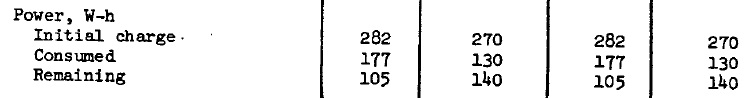 In second EVA, Conrad has used 177 watt-hour of electrical power, while he was predicted to use 130 watt-hour only, and, as he has used less oxygen and feedwater than predicted, he should also have used less electrical power than predicted. And Al Bean has also used 177 watt-hour of electrical power instead of the predicted 133, with the same comment as for Conrad. But the final clue is that Al Bean has used the same electrical power as Conrad, while he has used more oxygen and more feedwater than Conrad did, which means that he should also have used more electrical power! This is a proven incoherence! |
