|
|
Downloads |
Guestbook |
|||||||||||||||||||||||||||||||||||||||||||||||||||||||||||||||||||||||||||||||||||||||||||||||||||||||||||||||||||||||||||||||||||||||||||||||||||||||||||||||
| |
||||||||||||||||||||||||||||||||||||||||||||||||||||||||||||||||||||||||||||||||||||||||||||||||||||||||||||||||||||||||||||||||||||||||||||||||||||||||||||||||||
|
Controlling Stepper Motors You should read the articles about the parallel port and stepper motor if you want to use your PC to control stepper motors. Also, read about transistors if you want to control more powerful motors. It'll give you some idea about designing the best driver for your application. Computers are still the best way to control steppers especially if you want to do complex automation. Next, choice would be a microcontroller unit telling the stepper motor what to do. You can also make stand-alone (no PCs required) stepper motor drivers but they are really dumb. Stepper Motor Driver Using I/O board
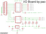
You can use the sample I/O board featured in the parallel port interfacing section. Two motors can be controlled simultaneously by the ULN2803 driver. I made a program in Visual Basic to control the motors.
You can try it on a breadboard using just the ULN2803. The 74LS244 and its sub-components can be removed since there are no input or feedback requirements. Four output lines will be used by one motor. You can use any of the eight available lines but for simplification let's use pins 2 to 5 of the parallel port. Connect the common wire of the motor to V+ together with the +12V supply. The other four wires of the motor will be connected to pins 18 down to 15 of the ULN2803. Resulting in Fig. 1.
Fig. 1 (Sample connection) Our program must be able to send a hi signal [ +5V ] to each pin used sequentially. Let's assume that the motor will move clockwise when we start from pin 2 of the parallel port down to 5 and back to 2. The motor will move counter clockwise when we start from pin 5 to 2 and so on. Remember that pins 2 to 5 are members of the DATA port and that the DATA port is 8 bits with pin 2 as the least significant bit. So, to move the motor we must send out the following values to the DATA port.
Table 1 (Moving the motor clockwise) Looking at Table 1, we only used d0 (which is also pin 2) to d3 (which is also pin 5) to move the motor clockwise. The yellow part is always 0 or a lo signal because they are unused. On the far right of Table 1 is the hexadecimal equivalent of the binary value that we will send out to the parallel port. Notice that the hex values are multiplied by two. We can make a simple program using multiplication and division coupled with a simple if..then statement.
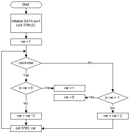
Fig 2. ( Program Flowchart for I/O board) What the flowchart simply does is to check first the direction ( clockwise/counter clockwise ) of the motor. Then it checks the value of var to make sure it does not have any value other than [ 1, 2, 4, and 8 ]. This is important because, the value 1 is assigned to pin 2 of the parallel port, 2 is for pin 3, 4 is for pin 4 and 8 is for pin 5. In case your wondering, the DATA port holds 8 bits right, and each bit corresponds to a decimal/binary/hex value. Below is a summary of the DATA port.
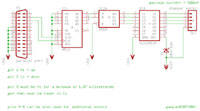
Table 2 ( DATA Port Summary ) Binary equivalent can either be 0 or 1 that is why it is represented like so. Further example, an 8-bit binary number like 0010 0001B is equal to 21H or 33 in decimal. So if you are moving clockwise (assuming clockwise starts from d0 to d3 from Table 1) you will use values in the range from 1 to 8 in decimal. If you are moving counter clockwise, you will start from 8 down to 1 and back to 8 again. Now back to the to the flowchart, if moving clockwise and our value of var is 1. It checks if the value of var is 8, if it is not then you will multiply var by 2. So 1 * 2 = 2, the value of var is now 2. Next it sends out the value of var to address 378H which is the DATA port. Now if for example, the current value of var is 8, the program must reset the value of var back to 1 because if you multiply 8 by two you get 16 which is not used. Division is done for the other direction starting from 8 down to 1 and then back to 8. Here is a sample program I made using Visual Basic. Remember Table 3 (Full Stepping ) from Stepper Motor Discussion, you were supposed to send 0V to the stepper motors and not +5V. Table 1 is contrary to Table 3 of the discussion. Why? Because we are using transistors (Darlington arrays in the ULN2803) and they are inverting the signals so we still get 0V even if we send out 5V. Better Stepper Motor Driver This "better" driver includes some ICs for decoding the sequences. It uses only two lines from the parallel port enabling you to control a total four motors. The circuit is more complicated though but the programming is easier compared to the first example. Click the thumbnail to view the schematic.
Here's a flowchart you can follow to make your program.
Fig 3. ( Program Flowchart for Stepper Motor Driver) What this simply does is set the direction bit plus pulse, wait for a small delay, then reset the pulse. What I mean by pulse is turn it on then turn off; from lo to hi and then back to lo. No more silly computations but instead we do three simple steps. Let's break it down: 1. set direction, 2. send to output plus pulse, 3. remove pulse. On the schematic pin 2 of the parallel port controls the direction and pin 3 is the pulse. A hi signal on pin 2 will set the board to move the motor clockwise ( this also depends upon how you wired the motor ) while a lo signal will set it to move counter clockwise. The activity on pin 3 from off to on and then back to off. The reason we set pin 3 back to off is to prepare for the next positive edge. If you leave the signal on pin 3 hi, the motor will not move again unless you reset it. The circuit is positive edge triggered. This means that an event will happen only when the transistion from 0V to 5V occur. How It Works The two additional ICs are CD4516, a binary up/down counter, and CD4555, a 2 of 4 decoder. Never mind if the driver used is a ULN2003, the only difference between it and the 2803 type is the number of pins. When I designed this circuit, I thought of it backwards. I considered the outputs first before the inputs. I really intended to use flip flops but after I finished the K-maps, it required 4 ICs plus a ULN to drive one motor. This was unacceptable because there are too many components, it will need a bigger PCB and will take more time to design a neat PCB layout. So I scrapped the very loooonggg computations and just figure out some other way to achieve my desired output. Now the output must be like that of Table 1 but requiring only two inputs: a direction pin and an enable pin. I always have a product list (from Alexan) on-hand when things really get low. I just looked up some possible components and thought about how they work and how I could use them in my problem. Well of course you need to have hands-on experience with ICs before you can even imagine how I came up with solution. EUREKA! The CD4555 accepts two inputs and provides 4 outputs. Any 2-bit input combination has an equivalent output of only one active pin. There is also an active low enable pin, for simplification, just connect it to ground. Here is the truth table from the datasheet.
Table 3 ( Truth Table of CD4555 ) So it is clear that only the inputs are missing. Notice that it counts from 0 to 3. Immediately, I looked up a binary up/down counter. It doesn't matter how many stages that it can count because you will only use the two least significant bits. Pin 10 of the CD4555 provides the direction of the count, it you connect it to 5V it will count from 0H to FH or 0 to 16. If the voltage at pin 10 is 0V then it will count from 16 down to 0. As I mentioned before, it doesn't matter how many counts it will do, you only need to count from 0 to 3 and vice versa. A CLK on pin 15 needs a positive edge pulse as an input. The counter will increment or decrement when the CLK detects a transition from 0V to 5V. You can use two CD4516 and one CD4555 plus one ULN2803 to control two motors. If you count up, you produce clockwise movement for the motor and if you count down, it moves counter-clockwise. A decade counter will not do because it counts from 0 to 9 if you convert it to binary from 0000 to 1001. If you reached 1001 you'll return back to 0000 and that will present a glitch in the motor movement. On the schematic, you can find a 1N4742A Zener diode, that's a 12V - 1 Watt type included to protect the current driver. You can omit this if you want to because the ULN already has built in protection. I used CMOS ICs for the simple reason of availability. Its not bad practice mixing TTL and CMOS as long as you operate in the 5V level. In fact I've been doing it for 4 years now and I haven't encountered any problems. There is an available level shifter from TTL to CMOS if you are using 5V for TTL and a different voltage for CMOS. Using CD4504, you can interface TTL with CMOS the correct way. You can also design the same circuit using 74LSXXX. You can use 74LS155 to replace CD4555 and 74LS191 to replace CD4516. Its really difficult to find them. You can also design a binary counter using 74LS types (JK flip flop) for the up down counter and 4 AND gates as a decoder. Check Texas Instruments and Fairchild Semiconductors for datasheets. Dumb Stepper Motor Driver Using a 555 astable timer and two SPDT switches together with the circuit above, you can make a really dumb driver. It can control the direction and speed of the motor plus an enable/disable switch. Instead of connecting the previous circuit to the parallel port use this for stand-alone operation:
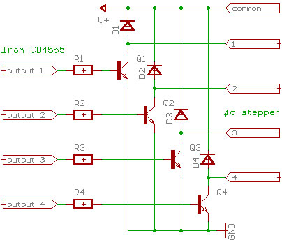
Fig. 4 ( Stand Alone Driver) Switch S1, enables or disables the motor, which is connected to pin 15 of the CD4516. Switch S2 determines the direction of the motor. S1 and S2 can be toggle or slide switch type. Potentiometer R2 sets the speed of the motor. The values of R1, R2 and C2 will be included in a separate section for timers. I use Electronic Workbench from EDA to simulate the timer. I cant find the documentation of the one I made in Feb. 2001 so please wait for the timers' section. Need More Power? If you need greater than 500mA load output, like when you're using powerful steppers. One solution is by cascading two ULN2803 ICs but the best way is to design your own current driver, its very easy. Please read about the article on Motor Driver Design. This circuit is similar to the example on the article.
Fig. 5 ( Current Driver ) You do not need ULN2803 if you are going to use this approach. You can determine the value of R via computation. The NPN transistors can be selected with the help of an Electronic Components Guide. Any 1N4XXX or 1N54XX type diodes will do depending on the application. revised 07-04-2002 orig 05-02-2001 |
||||||||||||||||||||||||||||||||||||||||||||||||||||||||||||||||||||||||||||||||||||||||||||||||||||||||||||||||||||||||||||||||||||||||||||||||||||||||||||||||||
|
|
||||||||||||||||||||||||||||||||||||||||||||||||||||||||||||||||||||||||||||||||||||||||||||||||||||||||||||||||||||||||||||||||||||||||||||||||||||||||||||||||||
| pao7/4/2k2 | ||||||||||||||||||||||||||||||||||||||||||||||||||||||||||||||||||||||||||||||||||||||||||||||||||||||||||||||||||||||||||||||||||||||||||||||||||||||||||||||||||