|
|
Downloads |
Guestbook |
||||
| |
|||||||
|
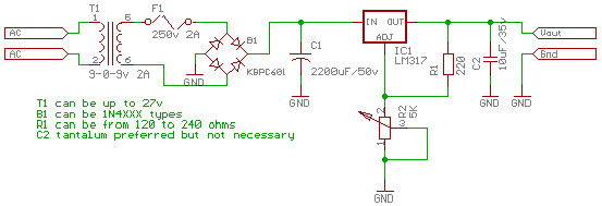
Variable Power Supply A simple variable power supply is a useful tool to every hobbyist. The project is based on National Semiconductor's datasheet about the LM317 voltage regulator. It should take about less than an hour to construct this project.
Fig. 1 (Variable Power Supply)
In the Philippines, we have 220 volts/ 60 Hertz mains. The transformer used is rated 220Vac primary and 9-0-9Vac secondary. The center tap was not used to give a total of 18Vac. The current of the secondary is 2 Amperes. It computes to an apparent power of 36 VA. You do not necessarily have to follow this rating, you can use any transformer as long as its secondary does not exceed 27Vac, but higher does not mean better. Usually, school projects do not need more than 1 Ampere and not greater than 24Vdc. I found the transformer lying around in my tool box so I used it. The 2A fuse is a 3AG type. If you will use a transformer besides the one rated above, do replace the fuse with a value that matches its secondary current. You can use any diode in the 1N40XX range for full wave rectification. Better yet, use a bridge rectifier B1, KBPC601 can handle up to 100V 6A. The electrolytic capacitor C1 used is adequate but if you have more budget then use a larger one. Or if you have 2 or more, you can connect them in parallel. Now the voltage across the capacitor C1 will be more or less 24Vdc. This will be the maximum voltage that our power supply can deliver. According to the LM317 datasheet, with a few other components, it can regulate voltage between 1.2V to 37V with a guaranteed output of 1.5 A. The output of the voltage regulator is also short-circuit protected. The LM317 will be the one to set the output voltage through the resistor R1 and the potentiometer R2. The resistor can be any value between 120 ohms and 240 ohms. The bypass capacitor C2 is there to improve stability. Some Improvements Click the thumbnail below to view a larger picture.
Notice the inclusion of the electrolytic capacitor C3, this improves ripple rejection. Two diodes are added to protect the regulator against the discharge of capacitors C2 and C3. I encourage you to build this one instead of the first. If you want to know more about the LM317, download the datasheet at National Semiconductor. orig 4-10-2001 |
|||||||
|
|
|||||||
| pao7/4/2k2 | |||||||