|
|
[] IowaZ Sitemap []
Send Email [] FZ1
Owner's Association [] IowaZ
Vmax Sitemap [] IowaZ
V65 Magna Page []
Use the FZ1
Sitemap to navigate all of the FZ
pages.
Yamaha FZ1
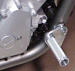
Foot pegs and case mod
Directions for making a plate to mount
solid foot pegs.
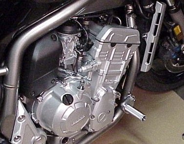
Overview
....The FZ1 needs a forward foot position
for longer trips. Sitting on a cycle day after day, for 300-500 miles is
much more enjoyable with adequate wind protection and a forward place to
stretch out the legs.
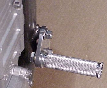
....An aluminum plate was fashioned to fit inside the lower two outside motor
bolts, onto which a attach a solid racing style foot peg that can also supply
a little case protection for tip-overs.
Cost and hints
....I called 1-888-fastlap, Marietta
Motorsports, http://www.1888fastlap.com
and requested assistance finding a foot peg that was tapped for a mounting
bolt. They indicated a solid peg was available that was tapped for an 8
mm bolt. Note: they are really tapped for a 10 mm
bolt. I could not find this peg in the current catalog and is not online
(May 2001). I am not sure of the envoice number, it may be 06-0300, CEM
HON PEG, $25 each, $5 shipping for a total of $55 for the two pegs.
....Bolts do not come with the pegs. I would wait until they arrive and
go to a good hardware store to select the correct length of bolts and washer
combination you want to use. Bolts and washers of choice should cost
$2-3.
....You will have to search around for a source of aluminum. I was lucky
enough to have a local rider that is an engineering student and machinst who
bought some high quality aircraft grade aluminum. Cost for
aluminum will be $3-5. Note: I used 1/4 thickness aluminum, but be
advised that the top mounting bolt is shorter than the bottom and when
everything is bolted back up, there is not full thread contact through the
inside nut. I might have considered 3/16 inch thickness, which I think
would have adequate strength. Or one can attempt to find a longer bolt
that will work. I am giving the present set-up a try before making any
changes (May 2001).
....Depending on your
"shop" you may need to buy some electrical jig saw blades and/or
drill bits. I had some basic power tools, but with some extra effort and time
this mod could be adequately accomplished with hand tools (hack saw, electric
hand drill, file, wet sand paper) and 'elbow grease'. The problem
however, when working with aluminum is its tendency to clog and stick to
drills, saw blades, files, grinding stones, sand paper
....Word of warning regarding sockets and wrenches. Go to Sear's (also a
few other places) and buy some high quality tools. Start with a good
6-point socket and wrench set (watch Sear's sales for an assortment you
like). Do not, do not, do not use 12 point sockets and wrenches, as they
will 'tear' up you fasteners. Twelve point sets make nice gifts for your
enemies. The motor mount bolts will be hard to break loose as they have
'lock-tite' on them.
.... Total time 2-5 hours depending on tools, skills, focus. Then
there is time ordering pegs and running after 10mm bolts and other basics.
....Total cost $60-65.
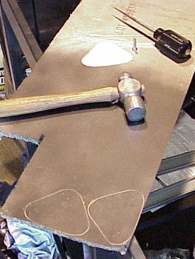
Desired tool and supply list
....Metric six-point socket and wrench
set.
....Drill press with correct bit sizes and center bit.
....Metal awl and hammer to mark drill hole positions.
....Sharpie Marker and dark spray paint to mark plating.
....Electric jig saw and several 12-14 tooth metal blades.
....Oil can with motor oil to cool drill bits and saw blades.
....Electric grinder to rough trip aluminum blanks.
....Electric belt sander with flat disk to semi-smooth plate edges.
....Electric grinder with buffering pads and rouge to rough polish plates.
Pattern Design
....You are going to transpose a
pattern of your own design to a piece of aluminum. File folder or other
heavy paper works well for the pattern material.
....Start with taking measurements. You can use mine but may want to take you
own. I have not placed my exact pattern dimensions online, as I feel you
need to closely examine your own needs and likes for peg
placement. One hint, a simple way to make the corners is simply to
select a circle of desired size and for each of the three positions
(top/bottom mounts and peg), draw the circles on the pattern and then connect
them with tangent line across the top from circle to circle.
....I started out with for me too large a plate and too elaborate of a
design. I ended up with a simple, small design. I like the end
product.
....One pattern will work for both left and right side as you will just use
the mirror or back side image for the other side. It is a good idea to
start labeling you pattern from the start, and also the aluminum when you
begin working with the blanks.
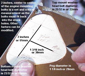
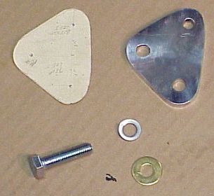
Measurements:
....Center to center of the engine mounting bolts is 2 inches or 51
mm. This is the most critical measurement as the bolts must fit into the
stock frame holes.
....Bolt lengths; top 4 1/2 inches, bottom 4 9/16 inches.
....Length to work with/threads showing; top 5mm or 7/32", bottom 7mm or
5/16 in (1/4" alum is 6+mm thick).
....Bolt diameters; top 10mm (3/8in drill bit), bottom 8mm (5/16in drill bit).
....Bolt head washer diameters; top 25/32" or 22mm, bottom 23/32" or
18mm.
....Foot peg bolt; 10mm (3/8in drill bit).
....Foot peg end diameter 1 1/8" or 29mm.
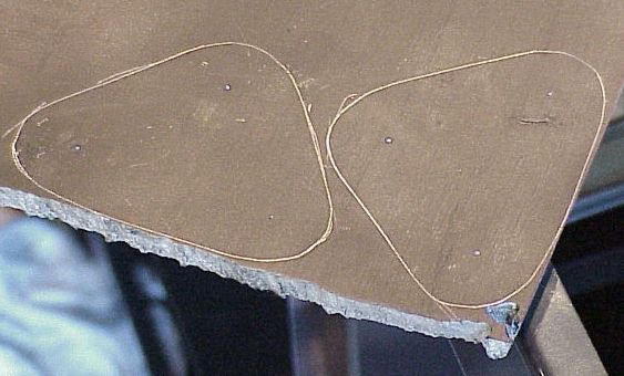
Pattern Transfer to Aluminum Plate
....Take a can of dark spray paint
and coat the aluminum plate so the pattern can be scratch on it for cutting.
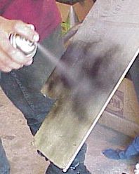
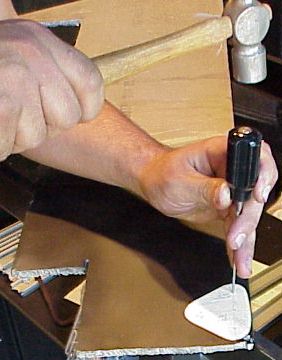
....A sharp point of a metal screw
works well to scratch the pattern onto the the Al sheet.
....Line the edge of the pattern near a straight edge of the sheet if possible
to eliminate more cutting than needed.
....Left/right is not an issue yet. Just mark off two blanks.
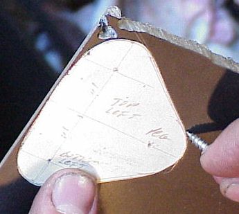
....It is a good idea to punch the position of the
holes that will need to be drilled after the blanks are cut out.
....The position of the drilled holes is
critical, especially the motor mount holes at 2" apart.
....This may be a good time to use a Sharpie pen and mark left/right blanks
and the holes (TL can be top left hole, as an example).
....Mark and punch both blanks.
Sawing out the Blanks
....Try to clamp the metal down do it
does not vibrate excessively while sawing. It will take a fair amount of time
to cut out the blanks so have good lighting and good positioning for sawing.
.....Install a new 12 or 14 tooth
metal electric jig saw blade in your saw.
....Stay just to the outside of your marking lines. Leave a little edge
to smooth off later, but not much.
....Use a small amount of oil when cutting or drilling, as it will assist the
blade/bit in cutting/cooling the metal.
....Be sure to get all the outside edges cut down before cutting the back of
the blank as it is hard to trim a small piece.
....Let the blade do the cutting but you will need to put a fair amount of
pressure on the saw as it cuts.
....Take your time, stop to wipe the savings away and reapply oil. It
will be hard to see the cut if you do not wipe the cutting area off
consistently as the aluminum shavings will stick in the oil. So clean
off the shaving and oil frequently.

Alternative.....If you do not have an electric jig saw, you might try a hack saw, but it will be some major work. The aluminum will stick in the teeth of the blade.
Rough Trimming the Blank Edges
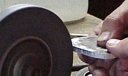
....The bulk of excess material
probably can be most easily taken off with a grinding stone. If your cut
is smooth and very near the line you desire then a belt/disk sander will be a
better choice, if both are available.
....If you do not have a way of
"redressing" your grinder stone, beware that grinding aluminum will
'melt' the metal into the pore of the stone and basically ruin the outer edge
of the stone. This filled in edge must be cleaned or dressed back down
to save the stone.
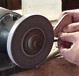
....Using the grinder to smooth out the blank edges to remove the extra
material and saw marks.
....A small belt sander will probably work the best to smooth out the edges and remove small amount of excess material. Beware of fine aluminum dust. It can be quit toxic. It out be best to work outside and wear a mask.
Alternative.....Trimming the cut edges might be accomplished with a file. Aluminum will 'fill' in the file grooves. Sometimes a very stiff steel brush will 'knock out' some of the metal.
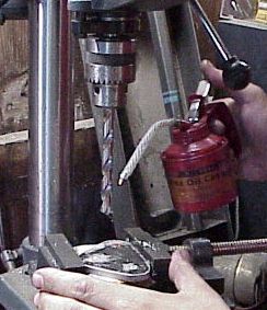
Drilling the Mounting Holes in the Aluminum Blanks
....If you have a center drill use
it at this time to make a pilot start for the drill bit. If you do not
have a center drill pit, you can use a smaller bit to start a pilot hole, but
just drill in about half the metal thickness. Use something like a
1/16" bit.
....Try to drill very accurate holes so they fit the motor mount stock holes
without a lot re-drilling or widening of the drilled holes.
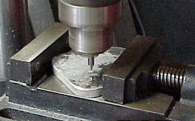
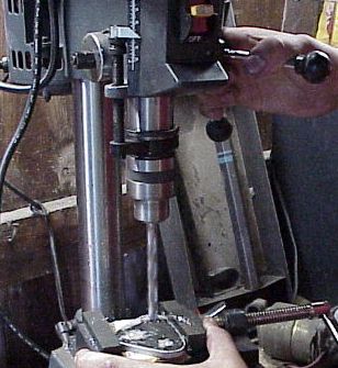
....Be sure to use a little oil
while drilling the plates.
Alternative....If you do not have a drill press, try your hand drill.
It is time to break the Engine
Mounting Bolts loose.
....After drilling the holes and before
going on to finish the plates, the engine mounting bolts need to be removed to
see if the drilled holes in the plates match up. If they do not they
will have to be enlarged a little so the engine bolts can be replaced through
the plate holes. If the holes need to be enlarged you can try a dermal
tool with a carbide reamer, a rat-tail file, or wobble a drill bit around the
edge of the hole needing enlarged.
Hint....take only one of these bolts out at a time, just in case there is a
lot of pressure on them and if both are removed the motor drops down just a
little and it becomes a major effort to "jack" the the motor back up
to get the bolts replaced. If it is very difficult to get a bolt out,
then there probably is a lot of pressure on the mounts. In that case
just remove one bolt at a time and slip it through the plate and back into the
original place, then do the other bolt to see if both match up. I am
guessing, like mine, that there is minimal pressure on these two bolt while
the bike is on center stand and that both can be removed at the same time.
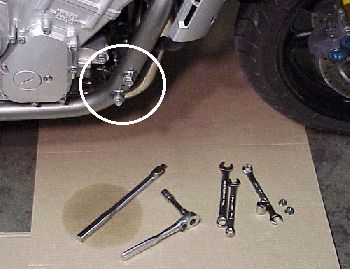
....The mounting bolts have
locktite applied at the factory and will be somewhat hard to bread
loose. Just apply a firm, hard pull on the bolt head while holding a
wrench on the nut, which in to the inside near the outside exhaust header
pipe. There is enough room to work without major difficulty.
Hint....invest in good six point sockets and wrenches. You will end up
rounding bolt and nut heads without them. In fact, the motor mount bolts
are tough enough to break loose that you may round these during this very
simple operation. I am a mechanical idiot, but still slowly acquire good
tools. I stick with Sear's when at all possible, because of the quality,
availability, guarantee, variety, etc. Take one of their tool catalogs and
highlight the tools, sockets, wrenches, etc. to keep track of your tool
inventory, as it help when shopping.
Hint....A ratchet may work to break the locktite loose, but I would use a
breaker bar. Ratchets tend to slip under force and round bolt
heads. I had all I could handle breaking my bolts loose using a breaker
bar.
....When you are certain the plate can be mounted to the bike, slip the bolts back in place and it is time to move on the the finishing/polishing of the plates.
Polishing the Mounting Plate
....A grinder with polishing pads works
best. I use two pads to balance the grinder motor and two grades of
polish, one for rough polishing and another for medium polishing. If
going to a mirror finish this process will take longer and more grades of
polish desirable.
....Since the FZ1 motor and the foot pegs have a brushed or unpolished look, I
left the plates with a similar look and not highly polished. It is a
matter of time/tools/choice of appearance.
....The plates can be whipped clean with thinner or alcohol, and sprayed with
a clear coat if desired, as aluminum will oxidize. Initially I have
chosen to leave the plate uncoated and moderately finished, as I am not sure
this is my final design.
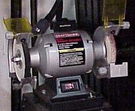

Alternative....Wet sand paper can be used to polish to a functional
level. Start with a coarse grit like 220wet and move up two or more
grade of fine. You might try some household level aluminum polishes
after the sanding.
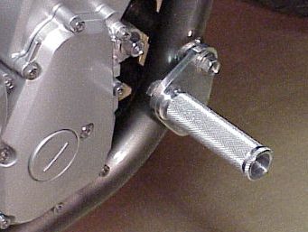
Mounting the Foot Peg to the Aluminum Plate
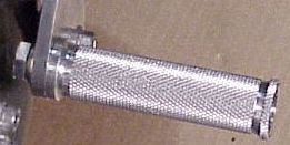
....Mount the peg to the foot peg
before before mounting the plate to the engine mounts.
....I used a brass washer on the inside next to the plate and then a lock
washer directly under the head of the bolt. The brass washer is not
needed, but I would put a lock washer in place. Firm the bolt up.
It is easy to hold by hand and tighten. Do not place a tool on the peg
to mare the finish.
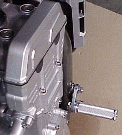
....Now the peg assembly is ready to mount on the FZ1 at the engine mounts.
Mounting the Peg Assembly to the Motor Mounts
....The hard work is done.
Slip the bolts out again and simply mount the peg assembly in place.
....You can use locktite on the bolt if desired. I am initially
just going to watch/check them consistently, as I may change the plate design
after a fair amount of testing.
....Snug the bolts down pretty firm, or if you have a toque wrench, the torque
on the upper or M10 bolt is 40ft-lb (55Nm), and on the lower or M8 bolt is 24
ft-lb (33Nm).
Hint....it would be a good idea to consistently check all bolts for awhile and to apply locktite to the nuts when satisfied with the assembly. You will need to search for longer bolts if there are not enough threads on the upper bolt to remain secure. There is very little lateral or side-to-side pressure on these bolts, most of the pressure is vertical or up-down.
....All done. Clean up, put the tools away, and go for a test ride.
Riding Impressions
.....Since these are solid pegs,
mounted solid to the frame and engine bolts, I initially thought the buzz from
the engine was too much, but after riding awhile I can easily tolerate the
buzz felt in the feet. The engine does not buzz through much of its rpm
range. Generally above 4k the buzz was not a factor. However, my
riding style is to put one foot out at a time to stretch the leg for
awhile. I never ride many miles with a foot on the peg, and rarely leave
two feet out on the pegs for more than a minute or so. Also I ride with
fairly thick soled Wellington style boots and to not put very much pressure on
the pegs. They will work very nicely for me.
....I did notice the position of the pegs are a little closer in compared to
My Vmax case guards which are about as far out as I like, while the FZ's are
about as close as I like. I only have a 30in inseam, thus even with
boots the FZ is too tall, however both sets of pegs have my legs in close for
riding. The Vmax is very similar in riding and peg positions, which is a
major reason I like the FZ, the other being the modern performance
level. A tall rider might consider a forward peg position below the
engine mounting bolts, but would need to be very careful about peg touching at
severe lean angles on corners. That could be an accident ready to
happen.
....The nuts on the motor mount bolts were secure after the first 80 miles.
....More to come after some longer rides where the legs need to be stretch
out. After the run to Elkhart Lake?? Presently my feeling is that
the pegs are right on the money for a shade tree job.
....Post Elkhart Lake trip: The pegs could not have worked better.
I like them a lot. They look good. Good enough to get compliments
at the track. They function perfectly for me to get one foot out at a
time for stretch. I usually do not ride with two feet up very
much. On this trip I had both out together about a half dozen times and
then not for anymore than several minutes at a time. The pegs worked
great for two feet out. The peg buzz is not a significant issue, in fact
I did not notice buzz very often. The pegs are more than worth the time
and cost.
Use the FZ1 Sitemap to navigate all of the FZ pages.
|
|
[] IowaZ Sitemap []
Send Email [] FZ1
Owner's Association [] IowaZ
Vmax Sitemap [] IowaZ
V65 Magna Page []


Any reproduction of this site or it's contents requires express written consent.
|
To Open a Search or Find-a-Word Window, press "Ctrl" and "F" at the same time. |