
Resurrection of a 1951 Zenith H2250R "Porthole" Television
I had wanted a Zenith porthole for quite a while when this set appeared on eBay. It was within a few hours drive from my location which was a change from what is usually listed. The condition was somewhat disappointing but I welcome a challenge.
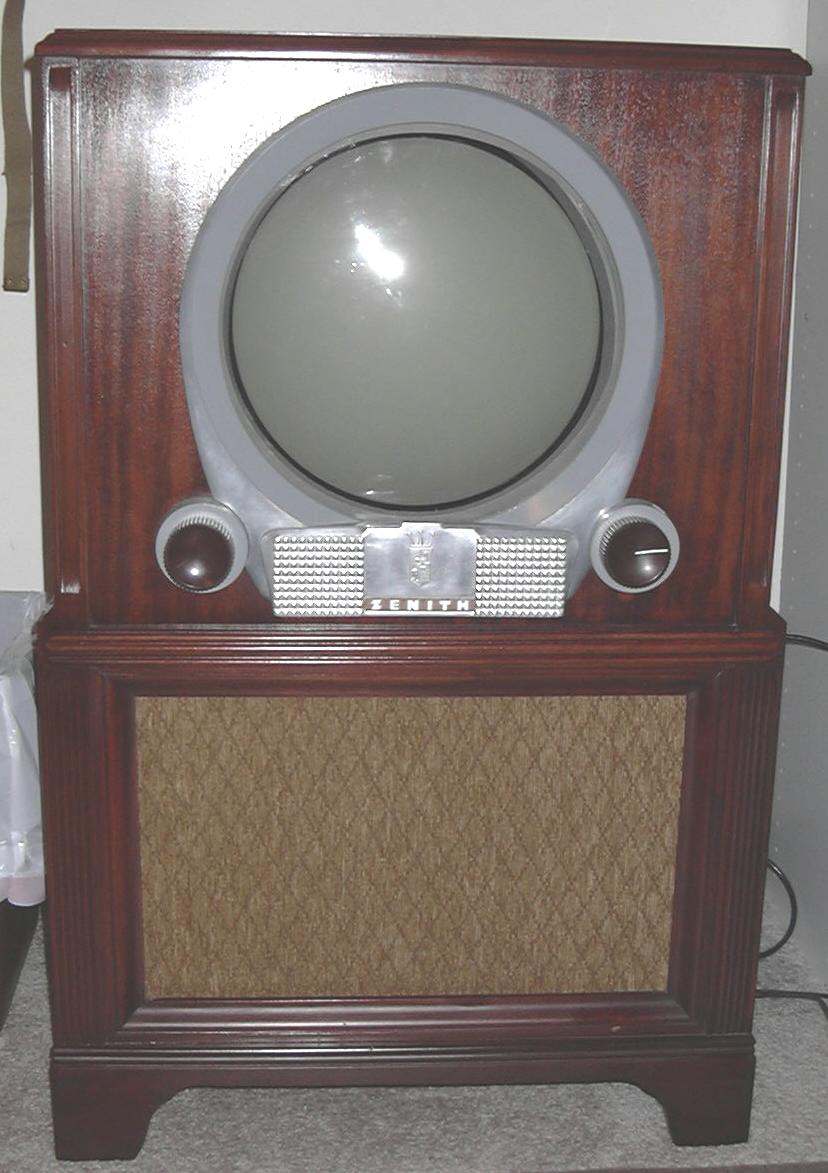
Below are a few photos of the set when I brought it home. The guy I bought it from said it was his grandfather's first TV. The set had been sitting in the grandfather's basement for some years and was showing that rather well.


Above are photos of the back before I did anything to the set. After cleaning numerous mud dauber nests, mouse gatherings, and dirt out of the cabinet I pulled out the chassis.
It isn't clear in these photos but the aquadag had started to flake off of the picture tube. One of the first things I did when I got the chassis inside was to pull out the picture tube. I packed it in a box full of styrofoam peanuts and set it off to the side to prevent breakage. I cleaned out the cabinet some more before bringing it inside to make sure I didn't bring in any unwanted 8-legged critters. The cabinet had quite a bit of water damage along the bottom. The finish was well beyond hope of revitalization so when I got the chance it was stripped and refinished.


These photos show the extent of the water-damage to the cabinet. The structure is pretty sound so that's a plus.
Before I started the electrical restoration, I checked all of the tubes. This set has 22 tubes including the 12-inch CRT (Chassis 22H20). The picture tube checked good on my checker after a little rejuvenation. Eight of the tubes checked bad. I planned to replace all of the electrolytic and paper capacitors in the set. The set has 13 electrolytics and 26 "Black Beauty" paper caps. I was able to obtain an original factory service manual on this set through eBay so I would have a schematic and alignment information.
|
Tube |
Function |
|
6CB6 |
R.F. Amplifier |
|
6CB6 |
Converter |
|
6C4 |
Oscillator |
|
6AU6 |
First I.F. Amplifier |
|
6AU6 |
Second I.F. Amplifier |
|
6AU6 |
Third I.F. Amplifier |
|
6AU6 |
Fourth I.F. Amplifier |
|
12AT7 |
Noise Limiter Inverter / Intercarrier Sound Amplifier |
|
6BN6 |
Audio Detector |
|
6BF5 |
Audio Power Amplifier |
|
12AU7 |
Video Amplifier |
|
6BN6 |
Sync. Clipper |
|
6SN7 |
A.G.C. Amplifier / Horizontal Control |
|
6BL7 |
Vertical Sweep |
|
6AL5 |
Horizontal Phase Detector |
|
6SN7 |
Horizontal Oscillator / Horizontal Discharger |
|
6BQ6 |
Horizontal Output |
|
6W4 |
Damper |
|
5Y3 |
Rectifier |
|
5U4 |
Rectifier |
|
1X2 |
High Voltage Rectifier |
|
12LP4 |
Picture Tube (Originally a 12UP4) |
The Restoration:
After replacing all of the paper caps and the bad tubes I decided to check out the chassis. I pulled the 1X2, 5U4, and 5Y3 rectifier tubes and plugged the set in. The filaments of the remaining tubes lit and measurement of the high voltage winding of the power transformer verified that the transformer was working properly. I unplugged the set, installed the picture tube, and re-installed the rectifier tubes. After the set warmed up I was able to measure about 10kV at the anode of the picture tube. I fiddled with the ion trap position but was unable to get a raster. After fooling with it some more I decided to check the continuity of the anode connection on the picture tube. The connection on the tube had a pretty high resistance so I cleaned it out with some contact cleaner and a cotton swab. I replaced the anode connection and powered up the set again. I could just sense that the CRT was getting high voltage now and after adjusting the ion trap again I was finally able to get a raster. I went through and checked all of the resistors and replaced the electrolytic capacitors in the chassis.


After examining the cabinet I determined that the sides were too far-gone to save. I found a sheet of 3/8" mahogany-veneered plywood in my stash of lumber, which would be a perfect replacement. The cabinet was almost completely taken apart. The top and front were taken off as one piece, both sides removed and the framework pulled off. What was left of the original finish was stripped off of the front/top piece while the cabinet was apart. New sides were cut from the plywood and I rebuilt the cabinet. The veneer on the front/top was almost perfect with only 2 small chips at the rear corners. Those chips were patched before beginning the refinishing.
With the cabinet put back together and sanded, I began staining with Minwax Red Mahogany. With all the staining done I finished the cabinet with two coats of clear lacquer. The grille cloth was also beyond being saved. I found a cloth with a similar pattern at a fabric store and used that to replace the original. The back cover was repainted and I made new control location and caution labels to replace the much faded originals.


The photos below show the two picture formats that can be displayed on the circular screen. A switch behind the controls door shorts changes the vertical sweep magnitude, which results in either a full circular screen or a normal 4 x 3 rectangular image. The width remains the same for either format. The full screen just makes the characters look thinner.


This set turned out pretty well, if I do say so myself. I spent a good six months to restore the set. I had a couple of problems pop up after I thought the set was done. While the chassis was still on the bench before I finished the cabinet, the horizontal sync went out. That turned out to be caused by a leaky mica coupling capacitor between the sync clipper and phase detector. Later, the flyback went out after the chassis was put into the finished cabinet. Luckily I found a N.O.S. replacement from Moyer Electronics.
I acquired an example of the "Lazy Bones" remote control that was offered as an accessory for the 1951 model year sets. This mechanical remote bolts onto the back of the turret tuner and connects to a shaft protruding from the tuner. The remote motor is actuted by a hand control attached to the set via a 17-foot length of 3-conductor cable. The contol has two switches that allow the user to change channels in either direction.


With as much time as I put into this set, I decided to sell it. Only because I acquired another porthole. A fellow collector decided to thin out his collection and had a model in the cabinet style I really wanted. So, I bought a 12-inch G2350Z from him along with a 10-inch Admiral. You can view a few photos of the new porthole here.
This site created and maintained by Sean Barton.
Last updated 10/02/2004.
