
Proposal
Introduction
Our team project is Power Line Appliance Controller. In this proposal report, we have a brief description of its operation, how we plan to accomplish the design, and why we should be given the contract of building our design. In this paper, we describe an interface that allows the use of the computer system to turn on or off a particular appliance located any where in the home.
The power line appliance controller design, to be constructed by the team members is simple and easy to use, with no complex circuitry.
Purpose
Over the years new inventions have made human lives simpler. In home these inventions have potential to completely change lifestyles. A power line appliance controller becomes an integral part in everyday life, to make it easier and simpler.
Persons who are more than likely to use the power line appliance controller are:
- Disabled – persons who may be crippled in someway e.g. being restricted to a wheel chair, they can turn on/off a device with just a press of a key on the keyboard
- Employees - households who may be at work all day and be extremely tired at the day’s end, when they get hone they can turn on / off any device e.g. microwave, television set, from one location
- Relaxed - persons who just like to relax and have tasks done for them prior to them getting to the devices e.g. having the microwave or coffee maker turned and the coffee or food maybe made before getting to the devices, or persons who just like to laze around.
Considerations
Before we go into our design we will like to enlighten you on the considerations and assumption made for our design. These considerations are as follows:
- Need to choose a frequency for the signal, which must be larger that than the 60Hz which is the frequency of the power line. It should not be a multiple of 60Hz either. We will preferably use 1 KHz.
- Need to detect the signal of the right frequency and amplitude because we don't want a power surge voltage spike to be wrongly interpreted as a signal.
- Need control circuitry to flip the state of the appliance (the flip-flop and relays)
- Wait a while before another signal is sent (this is to prevent toggling the appliance on and off many times on receiving one signal pulse)
- Once the appliance has been toggled after receiving a signal pulse, we will send out a handshake signal onto the power line.
- It is assumed that we can place a relay on the power wire going to the appliance and that we control the appliance by only controlling the power going to it.
Basic Operation
The project design is to control three appliances.
See Figure 1- Basic Operation of Power Line Appliance Controller Design
The basic operation of the power line appliance controller is outlined below:
Transmitter Side
Assembly Language
A program is written in assembly language, such that the user has the option to choose whether he/she would like to turn on/off a particular device. The user does this by pressing a specific key from the keyboard.
Parallel Port
If the right key is pressed the signal is sent via the parallel port of the computer, which is propagated to the multiplexer, which gets the control signals.
Counter
Since we are controlling three appliances a 4-bit counter is used. A 555-timer is used to generate a frequency, which is then transferred to a counter, which breaks it down to three distinct frequencies.
Multiplexer
The multiplexer sets the frequency and sends it to the filter and then to the power line.
See Figure 2 - Schematic of Transmitter
Filter
A filter is used as the interface from the transmitter to the power line and from the power line to the receiver end. This is necessary because the power line has its own frequency, so we do not want our signal frequency to be interfered with or by the power line frequency.
Power Supply
The power supply design is to supply the entire circuit design and all the ICs used.
See Figure 3 – Schematic of Power Supply
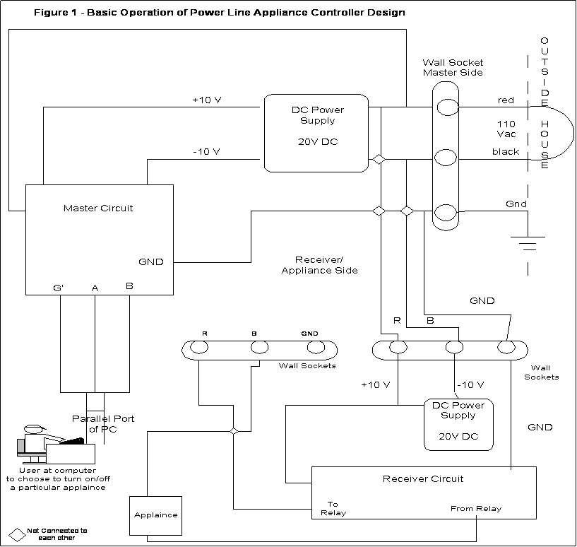
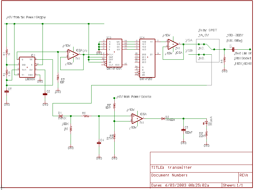
Figure 2 – Schematic of Transmitter
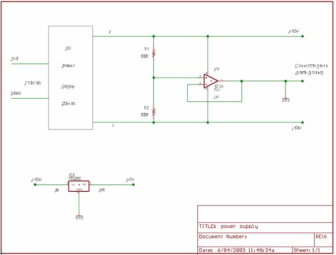
Figure 3 – Schematic of Power Supply
Basic Operation
Receiver Side
The receiver repeats itself for each appliance where the values of the resistors are manipulated to obtain the specific frequency for the particular appliance we would like to control.
Tone Decoder
This device detects a particular frequency and hence selects the particular appliance
Flip Flop
One signal / frequency is used to turn on or off the appliance. The flip-flop is used to toggle the options of turning on or off the appliance.
See Figure 4 – Schematic of Receiver

Figure 4 – Schematic of Receiver
Research Methods
All research and gathering of information was done via the Internet where we researched each segment of our design and obtained datasheets for all the IC’s. We also interacted, via email, with an Electrical Engineering Instructor, at the University of Florida, for background information and confirmation of our design.
Personnel
All team members have a background electronics and assembly language, which we gained at TTIT.
Team members involved in this design:
Isa Omardeen – Project Manager
Marisha Rawlins
Shelly Sing
Neila Maraj - Scribe
Requirements & Time Line
|
ID |
Activities |
Resource |
Duration |
Date |
||||||
|
1 |
Topic Acquisition
|
Team |
1 hour |
14th May |
||||||
|
2 |
Topic Approval |
Instructor |
2 days |
14th – 16th May |
||||||
|
3 |
Plan / Research
|
Team |
4 weeks
1 week 1 week 1 week |
14th May – 4th June |
||||||
|
4 |
Budget Plan
|
Team
Each team member was assigned a different company |
3 days
1 week |
2nd – 4th June |
||||||
|
5 |
Design Approval |
Instructor |
1 week |
4th June |
||||||
|
6 |
Select & assign tasks |
Team |
1 day |
16th May |
||||||
|
7 |
Acquiring money |
Team |
1 day |
4th June |
||||||
|
8 |
Progress Report |
Neila |
1 week |
2nd – 9th June |
||||||
|
9 |
Proposal Report |
Neila |
1 week |
2nd – 9th June |
||||||
|
10 |
Proposal Presentation
|
Team
Marisha |
1 week |
2nd – 9th June |
||||||
|
11 |
Acquiring parts & materials
|
Isa, Shelly
Isa, Shelly
Shelly |
1 weeks |
4th – 11th June |
||||||
|
12 |
Programming |
Marisha |
2 days |
7th – 8th June |
||||||
|
13 |
Build |
Isa, Shelly |
4 days |
26th – 29th June |
||||||
|
14 |
Test |
Isa, Shelly |
2 weeks |
26th June – 9th July |
||||||
|
15 |
Demonstrate |
Team |
1 day |
11th July |
||||||
|
16 |
Final Report |
Neila |
1 week |
26th June – 3rd July |
||||||
|
17 |
Final Presentation
|
Team Marisha |
1 week |
3rd – 10th July |
||||||
|
8 |
Website |
Neila |
on-going |
To be completed by 3rd July |
Figure 5 – Work Breakdown Structure
Budget
In our budget, we accounted for all the required materials for the successful completion of our Power Line Appliance Controller design. This includes resistors, capacitors, IC’s, diodes, etc.
Thus, our budget is set at $520.00
Deliverables
Based on all our requirements for the successful completion of our Power Line Appliance Controller project, the team intends to have completed all of the following within a defined time frame as outlined in the Work Breakdown Structure.
· Progress Reports
· Final Design of Power Line Appliance Controller
· Working Power Line Appliance Controller
· Final Report
· Final Presentation
· Website
Request for Approval
This project should be approved since:
· The final product would be beneficial to many people such as the disabled and busy employees.
· People today are concerned about convenience and saving time so this product would also be beneficial to them.
· The power line appliance controller can be produced at a low cost, (as indicated in our budget), so that it would be affordable to many customers.
· Appliances are prevalent in homes so we predict that there would be a high demand for the product.
Now that we have outlined our project we would like to request approval to move ahead with our project.
