The outfeed table which is available from Shop Smith works very well once mounted on the machine. The problem is getting it mounted. In my shop it cannot be left in place because my shop is long and narrow. I normally use the Shop Smith against a wall but when ripping long boards I have to turn it so the boards are along the long dimension of the shop. I have the caster package for my machine.The problem is that it requires 3 hands, or as you will see below two hands and a foot, to mount the table. I have devised a method of mounting that requires only two hands and no tools.
The Table as it Exists.
The outfeed table was shipped with a complete roller stand included in the box. Assembly instructions said to remove the roller and discard it. The bottom part supports the far end of the table while the near end attaches to the Shop Smith table. A piece of square stock that fits into the bottom of the roller stand is fastened to the outfeed table in such a way as to permit it to pivot in any direction. In the photo below the free end of the piece of square stock is held to the bottom of the table by a length of Gorilla tape.

The above picture shows the table leaning against the wall with its bottom showing. The bottom of the roller stand support is shown at right.The picture below shows the table installed. Although I neglected to install the rip fence before taking this picture there is room enough between the main table and outfeed table for the hold down on the fence to fit between the fence rail and the edge of the outfeed table.

A tube which is the same length as the rip fence guide tubes on the mane table slips inside as shown. A threaded cap is pressed into each end of the tube.

When this tube is pushed in so the ends are flush and clamped in place the screws can be installed through the brackets on the outfeed table to hold it in place as shown below. But getting it there is easier said than done.

Below I am holding the top edge of the table approximately level with my left foot while I use both hands to align and start the screw through the right hand bracket into the tapped hole in the plug. The table is vertical. The top edge is where the brackets are hold it to the main saw table.
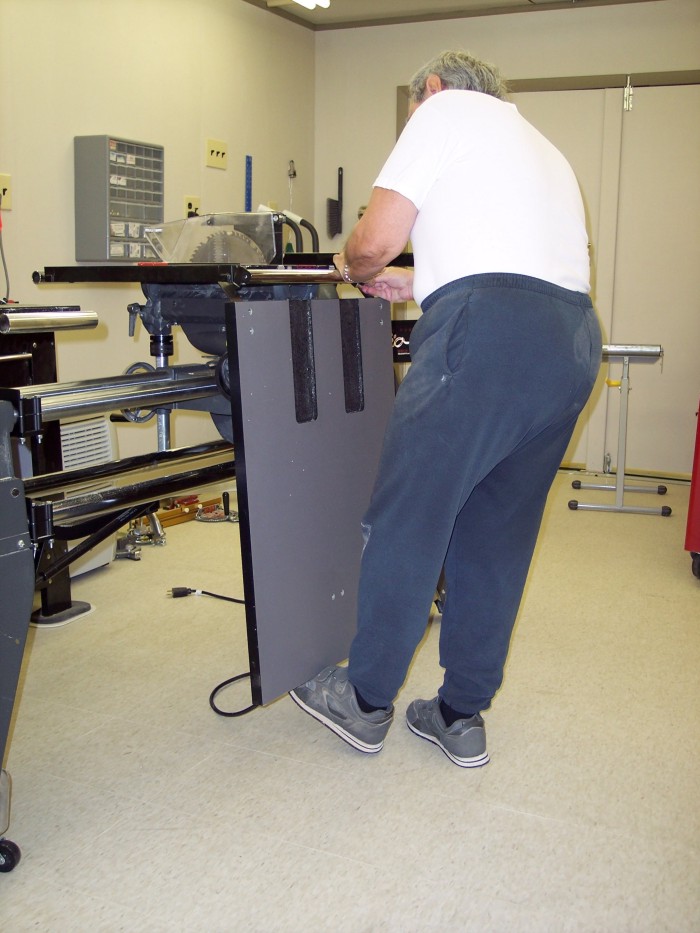
Then I hold the table level with my right foot while using both hands to align the left bracket and start the screw. Why I elected to change feet I don't know. Maybe my left foot got tired and I changed to give it a rest.

Next I used an Allen wrench to tighten the screws.

Then I used my head to hold the table in a nearly horizontal position while removing the Gorilla tape and inserting the square stock into the bottom part of the roller stand.

The final step is to level the table and lock the stand in place.

The Solution.
So let's replace the metal brackets with wooden ones and use one of the Shop Smith extension tubes which are longer than the fence guide tubes on the table. Below is a drawing of the wooden bracket.

Each bracket is a glue up of three pieces cut from a piece of 3/4 inch thick oak that is seven and a quarter inches long and two inches high. There is an arch near the left end which fits over the extension tube. At the right top corner there is a 4 inch by 1 and 3/32 inch piece cut out. Which the edge of the outfeed table fits into. At the top of the drawing is a top view of the support. It shows that the entire bracket is 2 and 1/4 inches wide. Three pieces of 3/4 inch thick wood glued together. The step which the edge of the outfeed table buts up against is 4 inches from the right end. There are two holes drilled vertically through the piece. One is centered 7/8 inches from the step and the other 2 and 3/8 from the step. They are centered along the 2 and 1/4 inch dimension. Bolts will go through these holes to mount the bracket to the table. The lower drawing in the figure above is a side view of the bracket. Don't worry about trying to keep the numbers added up as we move around the piece. Overall dimensions will be given later. Starting at the lower left corner we will move counter clockwise. The bottom goes horizontally for a distance of 1 and a quarter inches. This is the beginning of an arch. The edge goes up for a distance of one inch. Then it joins a semicircle which has a diameter of 1 inch, a radius of one half inch. The semicircle takes us up and over and we are now headed down one inch to the right of where it began. The line goes down one inch. We are now level with the starting point. Now we move 5 inches to the right. Then we turn and go up 29/32 of in inch. Then we turn and go 4 inches to the left. Then we turn upwards again for one and 3/32 inch. Then we turn horizontally again and go for three and a quarter inches. Then we go down 2 inches which brings us back to the starting point.Construction.
- Cut 6 pieces of 3/4 inch thick oak 7 and 1/4 inches long and 2 inches high.
- Use a Forstner bit to drill a one inch hole 1 inch from the top and 1 and 3/4 inch from the left end. Be sure to back the piece with a scrap piece to prevent tare out.
- Use some of the leftover oak to make a fence for your miter gauge that extends at least 4 inches to the right of the saw blade, assuming the gauge is in the left hand slot.
- Set the blade one inch high and cut a kerf in the wooden fence.
- Place the work piece in front of the fence with the top side up and the hole on the right, opposite to how it is shown in the drawing.
- If you have functional eyes line up the edge of the hole with the edge of the kerf in the fence, hold the work piece against the fence and make the cut.
- If not, insert a toothpick through the kerf at its top and use it to line up the edge of the hole with the kerf.
- Clamp the work piece to the fence and remove the toothpick.
- Then make the cut. The kerf should hit the hole exactly on a tangent. If it doesn't, it's not the end of the world.
- Perform the above alignment with the other side of the hole according to whether you do or don't have functioning eyes.
- Wait for the saw to come to a complete stop and remove the little piece which was freed by the last cut. It will not be kicked back because the fence prevents that. It will be sitting somewhere very near the blade and is a danger unless removed.
- Don't worry about the placement of the cuts relative to the hole for the moment.
- Turn the work piece over so the top is down. Turn it around so the arch is on the left. The open end should be up. Align the right end of the piece exactly 4 inches from the left side of the kerf in the fence. Clamp it in place. I advise clamping a stop block to the fence so you can make all pieces identical.
- lower the saw blade to a height of 29/32 of in inch.
- Make this cut on all six pieces.
- lower the table to give maximum blade height.
- Remove the miter gauge and install the rip fence. Install the feather board in the left hand miter gauge slot. You probably removed the blade guard for the previous cuts. Reinstall it now.
- Set the rip fence to be 29/32 inch from the near side of the blade. That is nearest to the fence. This is possible with the blade guard installed.
- You will run each piece into the blade with the open end of the arch toward the fence. Adjust the feather board to hold the piece firmly against the fence but make sure it is completely in front of the blade. You might want to raise the table and try a practice push through.
- When you are sure you have everything set up correctly turn on the saw and push the piece a short distance into the blade and then turn off the saw. Notice and remember where the end of the piece is relative to the feather board.
- After the blade stops, pull the piece out and examine it to determine how far the kerf went into the piece. Be sure to look at the side which was in contact with the table.
- If you are lucky the two kerfs don't meat. If you're extremely lucky they exactly meet and you won't have to do anymore work on that piece.
- Turn on the saw and push the piece into the blade again this time going a little farther relative to the feather board. Once again turn off the saw and after it stops pull out the work piece and see if you have cut far enough.
- Repeat the above step until the two kerfs meet. Remember the position of the end of the piece relative to the feather board.
- Repeat for the remaining 5 pieces.
- Now use a hand saw to cut through the remaining wood holding the scrap to the work piece.
- Use a wood rasp then a file to level the surface where the hand saw and table saw blade didn't quite match.
You now have six pieces as shown in the picture below.

Before applying glue let's do a dry fit. Place three of the pieces side by side on a scrap piece of plywood with the step cutout against the board. This is the surface which will eventually go against the table and it must be even. Clamp the pieces side to side and to the scrap piece. The part of the arch that was drilled with the Forstner bit should line up perfectly. The straight sides may or may not. Don't worry about it now.Remove the clamps and locate some wax paper. Place it over the piece of scrap that is the alignment and clamping jig. Apply glue to one side of each joint and put the three pieces back together and clamp them securely. Dried glue squeeze out will be hardest to remove from the arch so wipe it out now. Even if you plan to apply finish to the support this part will not be seen. Allow the glue to dry overnight.

Now that the glue has dried you can look to the arches. The kerfs that were cut into the piece should exactly meet the circle of the hole on a tangent. There may be some variation between pieces. If the kerfs were too close to the center of the hole so the sides of the arch bulge, remove some wood with a rasp, smooth it with a file, and finish with sandpaper.If the kerfs were cut too far from the center so there is a step in the arch cut some thin pieces of wood from the original piece and glue them in place to fill it in. To cut a thin piece with the Shop Smith set up the rip fence to cut off a thin piece but don't push the wood all the way through. As soon as enough has been cut, turn off the motor and pull the piece out. Use a hand saw to cut away the thin piece you need. Do not be tempted to use one long piece and glue it in cross grain. Use one thin piece for each piece of wood and glue them in place with the grain in the same direction. After the glue dries you can rasp and file them down to give a smooth arch.

Now mark the center of each bracket on the thin end inside the step. Your bracket will likely be less than 2 and Ľ wide, mine was. It seems that a 1 by 4 is now less than 3/4 by 3 and 1/2. If this keeps up, by the year 2100 you will have to buy a 4 by 12 to get anything thicker than veneer. But I digress. Drill two 3/8 inch holes in each piece both on the center line. One should be centered 7/8 inch from the step and the other 2 and 3/8 inches from the step. If you want to apply finish to the brackets, now is not the time.However you may want to do a little rough sanding to even up the edges of the individual pieces of wood. I used the oscillating spindle sander attachment for the shop smith to smooth up the edges of the brackets.
Remove the 3/8 inch machine bolts that hold the metal brackets to the outfeed table. Mount your newly made brackets to the table with 3/8 by 2 inch hex head machine bolts and 3/8 inch flat washers. Make any adjustments necessary to allow both bolts to go in.

If it is not already in that position place the table with its bottom up on your workbench or on the floor if your bench isn't big enough. Drop one of the Shop Smith extension tubes into the arches on the bracket. If it goes in without binding, congratulations. If it does bind loosen all four bolts so the brackets will move a little and align them so there is no binding. Hold each bracket in this position while you tighten the bolts. If alignment by this method is not possible you will need to remove some wood. Enlarging the bolt holes is probably the best first step.Now that you are probably through removing wood to make things fit you can take out the bolts and finish the brackets if you wish. I have left mine in natural wood.
Mounting the Outfeed Table to the Shop Smith Table.
Insert one of the extension tubes in the rear rip fence rail, adjust it so it sticks out equally on each end, and clamp it in place.Insert the square stock on the outfeed table into the stand and clamp it. I store my outfeed table like this. It stands against the wall and takes up little space. The outfeed table should now be hanging down with the new brackets at the bottom edge.

Lift the lower edge of the table.

Line up the arches with the extension tube.

Drop the arches over the tubes.

You may be wondering why I didn't start from the point with the table mounted on the stand when using the Shop Smith supplied brackets. That precluded me from using my foot to hold the other side of the table while I aligned the hole and started the first screw. I had to call upon Sue to come out and hold one side while I started the first screw.You may also be wondering why I didn't glue up the three uncut pieces and cut them as a single piece. I didn't think of it. Why didn't I use a band saw to make the cuts? I don't have one, or at least I didn't have one at the time I did this project.
Back to Woodworking Projects Page.
This page last updated November 17, 2009.