Max's Shop.


The small building now known as the Teddybear Cottage, herein after called TBC was too small for a shop but was just right for Sue and her craft work. She wound up with it and I bought a 12 by 30 foot building for my shop. It was delivered in exactly the same way as the TBC had been so there aren't any pictures of that process here. Actually, I didn't take any still pictures, for this event I got out the video camera. The still pictures begin after installation.

Time Line.


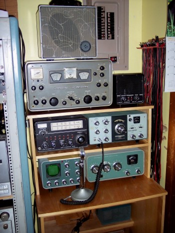
I started the Ham Radio Desk, here in after referred to as HRD shown above, sometime in December of 2006. Work started in the Lawnmower House but that was much too small. On January 3, 2007, with Sue's approval, I ordered a 16 by 10 building from home Depot which was delivered on January 30, 2007. Work resumed on the HRD, and it was completed sometime in March of that year. It was built using hand held power tools which were operated by dragging an extension cord from the building to an outdoor outlet located on the carport. The work of assembling and finishing the HRD took up most of the floor space in the little building. The addition of even a table saw would have taken up the small amount that was left. There was no doubt that this building was much too small.

Almost from the day the TBC was delivered, Sue had started talking about getting a building of her own. I guess she had a case of building envy. As I came to the realization that I wanted a bigger building I also wanted a Shop Smith machine. Sue and I made a deal wherein she would buy the smaller building from me and give her approval to buy the largest building that the Mennonites made.

They have a 1 month delivery time so we must have ordered the 12 by 30 foot one on or a little after April 21, 2007. It was delivered on May 21. The Shop Smith had been ordered a little too soon and came in earlier in May. The delivery company would not unload it from the truck. I prevailed on my best friend, John Smith, who owned a pickup truck. He brought three friends of his, Martin Cohron, Kevin Duckett, and Wendall Myers. Together we off loaded the crate from the delivery truck to the bed of the pickup and from there to the smaller building. They were anxious to see what it looked like, and so was I, so we opened the crate. The thing was mostly in pieces but they got the idea.

After the Shop building was delivered Sue and I moved the pieces of the Shop Smith from the TBC to my shop. The biggest single piece was too heavy for the two of us to lift. We partly slid and partly rolled it onto a big piece of heavy cardboard and skidded it across the yard to the shop building. We managed to put it together and it worked. Unfortunately I failed to record the date I cut my first piece of wood on it.

With the shop building on-site and the Shop Smith inside it work could be done employing the extension cord again. First project on the Shop Smith was mostly in June of 2007 building steps for the TBC and the people door of the shop. Next step was a ramp from the carport pad to the roll-up door of the shop.

Getting permanent power to the TBC and Max's Shop, as it was now called, was a high priority. Fortunately there were 4 unused breaker spaces in the main electrical panel. Two single 20 amp, and a double 30 amp were installed in the empty slots. The box can be seen in the picture of the HRD above. It was decided there would not be a 240 volt outlet in the TBC, the two 20 amp breakers were for it. The main panel is exactly where you would expect it to be, just on the other side of the wall from the electric meter. The meter is visible in the picture below.


What's in the picture?

On the left is the corner of the shop and we are looking almost straight down its side. The air conditioner is seen sticking out through the side of the building. The thin white object in the foreground is a piece of PVC pipe which is over one of the tower's guy wires to make it more visible.

In the background, behind the guy wire, next to the main house, is a sheet of treated plywood covering the crawl space entrance. To its right is the garbage container sitting on another piece of plywood. To the right of that is a small structure which houses an emergency generator. Yes, it is not tall enough to stand up in. At the other end of the ladder is the air conditioner unit and a little more to the right and above is the electric meter. At the right edge of the picture is the corner of the TBC. This picture was taken just after a rain.

The two sets of 4 conductor cable, number 12 for the TBC and number 8 for the shop, I'm not opposed to a little over design, leave the breaker box, and go down into the crawl space. The number 12 cable goes into conduit, through a preexisting hole in the wall, down underground, and comes up into the TBC and into its 2-circuit panel.

The number 8 cable runs as indoor wire in the crawl space until it reaches the crawl space access hatch. There it makes a transition to underground rated wire, enters conduit, and tunnels under the wall surrounding the access hole. The conduit emerges from the ground under the shop and goes right up to the circuit panel. There are 2-240 volt circuits, one for the air conditioners, (these are 120 volt units, one on each side of the line), and the other a spare for some powerful machine I might buy in the future. There are 4-120 volt circuits, 3 for outlets and 1 for lighting.

There is one feature which I think is unique. Every electrical outlet has a switch next to it for turning power to the outlet on and off. How many times have you read in an instruction manual for a power tool "… unplug the machine." I don't have to unplug it, I can just throw the switch.

Bringing in the electrical power to both buildings and finishing the wiring in the TBC takes us into July 2007. Sue and I worked together on finishing the interior of the TBC from July 5 through November 5. From then until Thanksgiving, we rested and were thankful.

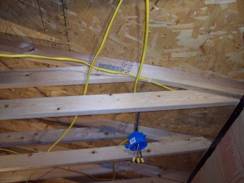
In the four months of TBC finishing I was also able to install ceiling joist in the shop and complete electrical wiring on evenings, rainy days and other odd moments. Shortly after Thanksgiving my on-again-off-again job was on-again. That combined with cold weather stopped work on the shop until May 2008. By then the weather had warmed up and I was off work again. The insulation was installed during this month.

Sue made good on her promise to help me finish the interior of my shop as I had helped her finish the TBC. We had a late spring in 08 and the temperature in May was mostly in the 70s. Installing the wall insulation was much more pleasant than it otherwise might have been. The ceiling was another story. The temperature in late May and June climbed into the 90s. The last staple was driven at one o'clock P M, CDT, on June 13, 2008. With the insulation in place we could run the air conditioner and keep cool no matter what the weatherman decided to throw at us.

Somewhere in the middle of the insulation, about June 1 a decision was arrived at with regard to the roll-up door. This door is large being 9 feet wide and almost 6 and a half feet tall. It is made of sheet steel and because it does in fact roll up does not lend itself to any form of insulation known to me or John Smith who is my main consultant on matters constructional. Aside from being a major conductor of heat between outside and in, it is inconvenient to work around and over. At John's suggestion I decided to remove it and replace it with a double swing-out door with insulation built in. John gave me some of his time and the use of his pickup truck and the materials were purchased on June 17, 2008. The construction was begun on the following day.

We only got in a few days work when John called me back to work. (Technically, he is my boss, but he is the best one anyone could ask for.) I didn't get off work again until August 12th. This brings the doors very close to being finished.

One more thing happened in this time period. It seemed that the 10,000 BTU air conditioner which was purchased last year was a little too small. On a 95 degree day the inside temperature rose to about 83 degrees. The humidity was low and it wouldn't have been uncomfortable to just sit and read. However, that's too hot for hard work. I am aware that insulating the door will improve the situation somewhat but probably not enough. After some looking around we found the identical unit at Target. It is still in its box but after the door installation is completed, the second air conditioner goes in. That is actually likely to be more economical than buying a single larger unit because on a relatively cool day I will only need to run one of them.

Painting the doors and the new wall sections went rather slowly in the second half of August and early September. You don't have to tell us to get a life. We are involved in other activities and they doo sometimes take us away from work on the shop project. We don't have any deadline to worry about. It will be finished when it's finished.

The doors were hung on September 10, 2008 after 24 actual working days.

With the newly installed insulated doors in place the temperature inside the shop could be maintained 15 degrees below the outside temperature. That's better but the second air conditioner will still be needed to maintain a comfortable working temperature of 70 degrees in the shop on a 95 degree day.

The second air conditioner was installed, a couple of light fixtures moved, and the roll up door taken down.

The construction of Woody II brings us roughly to the middle of October and apparently to the end of hot weather. Looks like we won't need any air conditioning until next summer.

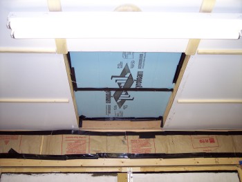
The ceiling paneling was purchased in October. We ran into a snag when trying to install the paneling. Then I had to go to a blind handyman gathering in Houston, then a State ACB convention, and then Sue and I came down with colds. By the time we got over them there was Christmas shopping to do, bowl games to be watched, and of course, the Florida Gators had to be cheered on to a national championship. A number of other distractions and diversions took the best part of January. So maybe we can get back to work after the Super Bowl.

Ha!. Famous last words. January turned into February which spun into March which slithered into April which morphed into May. Cold weather wasn't the reason because it was possible to keep the shop with its insulated door at a comfortable temperature and rain was no excuse either since everything could be done inside the shop. I think it must have been our failure with the blasted first ceiling panel. See below. With that issue overcome work continued. The last ceiling panel was put in place on June 4th 2009, the last light was put up on June 7, and the last poplar strips were nailed up on June 8th.

With the help of John Smith and his truck 20 sheets of 1/2 inch plywood for the walls were purchased on June 26th. The first panel was screwed to the wall studs on July 3rd. The last one on July 22.

On July 23 we went to Lowe's at 8 PM and bought the primer, paint, brushes, and rollers, needed to paint the walls. All painting was finished on the 28th. We didn't work Friday, Saturday, or Sunday. The whole painting job was accomplished in two days.

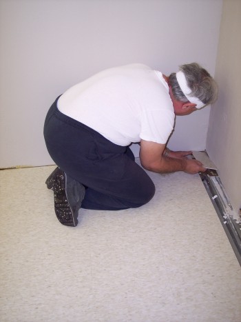
On the 29th in the afternoon we bought the flooring. Installation began on the 30th. The last tiles were laid on Thursday August 13.

On Friday the 14th John and his truck assisted in buying and hauling the materials for the wall which will make a storage area at the back of the shop. On Monday construction of the Great Wall of Max and Sue began. The storage area including 88 linear feet of shelving was finished on September 1, 2009.

The final step was painting the great wall and pre-painting the molding. The molding was painted on the car port to avoid getting paint on the beautiful new floor. The last piece of molding was installed on September 10, 2009.

Somewhere between the above date and October 2 the dust collector was removed from it's shipping carton and assembled. Surprise! It's too big for the space allotted in the storage room. On the second we took some space away from shelving and gave it to the dust collector as shown at the bottom of this page.

By definition that's all. If any more issues come up they will be defined as a different project. THE SHOP IS FINISHED!!!!!

The pictures and text below will document the shop construction. I must give much thanks to Sue for her help. If we had known how much work it was going to be and how long it would take I wonder if we would have started. If I had done it alone it might have never been finished.


The electric utility and telephone service lines were underground. The cable TV feed was above ground and ran across where I wanted the shop building. That fact had slipped my mind and it was a race to see if the shop would arrive before the cable service was moved over a few feet. The cable people won the race and the building could be placed exactly where I wanted it without knocking down the cable line and making the company very unhappy.


Shop Smith had won the race with the building manufacturers. With a lot of help from my friends I off loaded the shipping crate from the delivery truck and put it in the small building which had not yet been officially turned over to Sue. After the shop arrived we moved it over, I still don't know how, and assembled it.

To give the picture some scale, the studs in the wall are on 24 inch centers.


Then the job was to build a ramp from the carport pad to the role up door of the shop. This, so heavy loads of lumber and large machines could easily be moved into the shop.

The first step was placing the 2 by 4 stringers and digging their low ends into the ground so the boards would be level with the concrete pad. At the shop end they were fastened to the shop building with pocket hole screws, which is rather like toe nailing. Each 2 by 4 was mounted with 4 woodscrews, 2 on each side. Needless to say these are treated boards.

Next, the deck boards went on, fastened with woodscrews. These are actually deck boards. When the boards met in the middle, the gap could have been filled with one full board and about an inch of another one. Instead I ripped two boards to equal width to fill the gap.

The large fan which is visible inside the shop door in the bottom picture is the industrial strength fan referred to on the Teddybear Cottage page.


As delivered there were no ceiling joists in the building as the left picture shows. The large X is reinforcement that the builders had added to absorb stresses during transport and placement on-site. The delivery man removed these and asked me if I had any use for them. My answer was an emphatic "YES". In fact, two of them became ceiling joists. The picture at the right shows how they were installed. The joists were fastened to the stringers with 2-1/2 inch woodscrews.


Installing the insulation began modestly with 4 bats along the back, 12 foot, wall.


This picture shows the same back-right corner as shown above. By this time I had acquired more than the Shop Smith. There are 2-tool storage chests and a small workbench. These items had to be shifted around the shop as work moved from one area to another.


The installation of insulation proceeded. It was being fastened to the studs and plates with staples fired from a pneumatic stapler that I wish I had possessed during the finishing of the TBC. The paper along the sides is doubled but on the ends where it is single thickness the staples tended to tare out. The addition of a layer of Gorilla tape cured this problem. Although it looks like there is a continuous strip of tape along the floor and ceiling plates, it is really one length for each bat of insulation.


To maintain the vapor barrier more of the Gorilla tape was applied around the electrical boxes. Here you see one of the 120 volt double outlets with its on/off switch.


In this picture Sue does a little sweeping up after all the stuff has been moved from the left side to the right. The amount of stuff that needed to be shifted every time a different part of the shop had to be worked on is only hinted at in this picture.


It took us two days of hard work for the empty spaces to be filled in. A professional probably could have done it in an hour but we are taking our time and getting it right, something you don't always see in professionally done construction.


As with the TBC an attic fan was installed and provision made for an access hatch in the event that the fan ever had to be worked on or replaced. The roll-up door, which literally rolls up when opened, presented a considerable obstacle to the initial installation and to future maintenance work.


The ceiling presented some special problems mostly caused by the builder. That would be me. The shop building was constructed with studs and roof trusses on 24 inch centers. If I had placed the ceiling joists consistently on one side or the other of the trusses installation of the insulation would have been much simpler. However the lighting electrical boxes I had bought at the home center were supported by metal rails that fasten to a joist on each end. The ones I had on hand weren't quite long enough to reach 24 inch center placement. So - wherever there was a row of lights between joists I placed each one on the side of the trusses closest to the lights. That made the lighting boxes mounting rails reach but placed some joists on 27 inch centers. A strip had to be cut off a new bat and then taped to a normal one to cover the extra width.

Meanwhile, the narrow spaces were on 21 inch centers. The middle picture shows Sue cutting down a normal width bat to fit the slightly narrower opening. No, the off-cuts were not big enough to be used to pad out the bats for the wide openings. Some overlap of vapor barrier was necessary to give the joint a little more strength. As a result we ran out of material with only this much left, plus the spaces around the fan access hatch at the front.

You may be wondering about the tape at right angles to the joists. The building is nominally 12 feet wide which meant that each joist space needed one and a half bats. The very first one we did, not shown in any pictures, was cut to length, patched to width, and put completely together on the floor. Getting it up was a real bear. Not of the teddy variety. It wasn't heavy but highly unwieldy. It was like trying to jam a 12 foot snake into a bag he didn't want to go into. In the next one we put up the 8 foot section and then the 4 foot section. We did three that way and you can see one at the top of the top picture. Finally we wised up and cut one in half, placing each half at the end of a space. Then we measured the remaining opening and cut a piece to fit the space allowing 2 inches of overlap of the vapor barrier on each end. Handling these smaller pieces was much easier.


Here you see the end of the line. In the top picture I am attempting to hold up one third of a bat and tuck the end in on top of the ceiling plate. Normally, Sue would be on the green ladder holding up the other end, but she was standing on the floor taking the picture. The picture below shows me driving the last staple on the last bat of insulation. That was cause for celebration. The time stamp on the picture is one o'clock P M on June 13, 2008. That is Central daylight time.


The blue polymer foam is a temporary covering for what will eventually become the access hatch for the attic fan. The two bats on either side farthest from the camera are also temporarily stuffed in place because the conventional way of fastening was impossible with the roll-up door in place. You can easily see where the door has been rubbing on the joists. The door is slated to be replaced by a conventional double swing-out set of doors. After the roll-up door has been removed the fiberglass insulation will be installed in the usual way including on top of the access hatch which will likely be half the size of the present location of the blue foam.


The roll-up door is mounted entirely inside the building. That makes it possible to construct the replacement within the wall space while the old door remains in place. This meant there would be no security problems during construction. With the kindly help of John Smith the materials for the new door were purchased on June 17, 2008. The construction began the next day. The top picture shows the fruits of that first day's work. We began with a cutting mistake which wasted one two by four. "Oh well, we'll buy another one tomorrow."

The second picture shows the addition of a second 2 by 4 which was fastened with glue and screws. These will be the stationary door posts for the double doors. Each door will be 3 and a half feet wide which promises to be a rather heavy door. It will be made of siding and trim and will closely resemble the doors on the Teddybear Cottage which can be seen elsewhere on this site. The third picture shows the siding and trim. It will eventually be painted to match the rest of the building's exterior.


Here are the almost finished doors. The basic door panel is cut from the siding material that covers the entire building. The hinge side of each door has a double 2 by 4 for strength. The rest of the door is stiffened by a frame of 1 by 4s with 1 by 4s for bracing in the middle. The 1 by 4s are fastened to the siding with 2 inch brads. Reinforcement blocks at the corners are fastened with screws through all 3 pieces of wood they touch. The siding panels are also screwed to the double 2 by 4. The screws also pass through the trim pieces where they fall on opposite sides of the siding panel. The hinges and hasp will need to be mounted to these trim pieces but the screws will be long enough to penetrate into the double 2 by 4 or bracing blocks on the other side.


At this point we just couldn't resist standing one of the doors up in place to see what it would look like. The fit is as good as can be expected considering that the opening we had to work with is not square. At this point in time the building has been in place for more than a year. Settling has thrown the whole thing slightly out of square. The double 2 by 4 door posts are parallel to each other because we installed them. The top and bottom are humped up in the middle because the outside skids settled a little more than the center. The error is about 1 degree at the top of the opening and 2 degrees at the bottom.


Of all the tasks involved in interior finishing handling insulation is without question the most unpleasant. Sue cuts the second piece of insulation to size. Only two more to go after this one. They need a little extra cutting at the corners because of the reinforcement blocks. Sue admires her handiwork just before the 1/4 inch plywood cover goes on.


Caulking the cracks is very important. Any water which gets inside the door will quickly degrade the insulation and eventually lead to the growth of mold which will require this job to be done again. Neither one of us wants to do this again so Sue applies silicon rubber caulk to all openings. Similarly, if water gets under the trim and then freezes, the trim will be broken by the expanding ice and will have to be replaced. Never again will we repeat this work! We will likely use many tubes of this caulking material.


Now for the painting. We managed to make a perfect match with the existing colors. Having a small piece of the original siding from the cutout for the air conditioner helped a lot. The doors are finished. A little primer, and the colors on the outside wall sections, and the doors will be ready for hanging.


Then came the moment of truth, hanging the doors. In this picture the right-hand door has already been hung while the left-hand door leans against the wall awaiting its turn.


The grand opening. The first time a newly hung door is swung out is a tense moment. Will it squeak and grown? Will it sag? Will it fall off? It didn't do any of these.


After hanging the left hand door, Sue got to do the honors and open it for the first time.


This is a major milestone and we are glad to have it finished. I wish it had come out better. The bottom of the two doors collided and some wood had to be removed. Moving up, there is a progressively wider gap between the two doors and I hope we can manage to fill it in. One nice thing about painting, you can hide many mistakes. The right-hand door has a bad warp that may not be fixable.

Upon showing the finished doors to one of our children, there wasn't even a hint of criticism from him. Teddybears like cats and dogs give us unconditional love and never speak a discouraging word. Unlike cats and dogs they never have to visit the vet and if proper care is taken, they can live a very long time.


Next step was to install the second air conditioner. This required moving some outlets and connecting wires. The planned location for the second AC was in the largest vertical space where the insulation has been cut away. The switched 120 volt outlet on the left needed to be moved to the other side of the stud and the wire that connects between it and the one in the stud space next to the existing AC had to be rerouted.


Sue and I were too busy making the cutout and mounting reinforcing boards to the studs to take any pictures. Here the second AC is already in place.

After turning off the breaker the outlet and switch were removed from the box. To my surprise the large nails came out without bending. That meant the same box and nails could be used on the other side of the stud. Checking through my leftover wire I found that the longest piece was about 6 inches too short to span the required distance. That meant a trip to the home improvement store for a 25 foot package of number 12, two and ground.

To the left, out of the picture is a door and the breaker box is on the other side of that. The original source wire passed through a hole in the stud and then went up over the door and down to the main panel. After the source wire was pulled back through the hole it was plenty long enough to go into the box at its new location.

At the time I did the original wiring I didn't know what kind of AC I would wind up with. I mounted a double 240 volt 20 amp breaker and ran number 12, three and ground to the box. I removed the old single outlet box and replaced it with a double and mounted two 120 volt 20 amp outlets in it. One outlet on each side of the line.


Above the AC a horizontal length of 2 by 4 is mounted with pocket hole screws. This provides an anchor for the insulation and the upper end of the angled piece of plywood which diverts the outlet air into the room. This is easier to see in the AC on the right. Some leftover lengths of 2 by 4 were angled cut and ripped to width to fill in the gaps between the AC and the studs. The stud space at the second location is ½ inch narrower than the one on the right.

The second AC was installed as identically as possible to the original one. Fortunately we had a few leftover pieces of insulation to reinstall around the new AC. When the patched insulation is covered by plywood paneling no one will ever know that the two air conditioners were installed at different times.


There was one more side job that had to be done eventually so it might as well be now. Due to a redesign of the storage area at the back of the shop, the lights that will illuminate it had to be moved closer to the back wall. The before picture, left, is a repeat of one above while the after picture, right, is new. The insulation had to be cut away and the light box slid back on its track as far as possible. Then new pieces of insulation were cut, taped, and stapled, in place. The box mounting can be seen in the left picture below.


Now that the doors are finished and able to be locked the roll up door needs to be removed. Easier said than done. My best friend John Smith came out and with some help from Sue we managed to get it down. The edges of that sheet metal door are very sharp and we didn't get it down without a little bloodshed. Nothing large enough for the emergency room. Sue applied some first aid and work continued. All I can show are before and after pictures. All hands were needed on deck so there aren't any pictures of the process. The before picture is an older one which was selected to show how the roll up door was mounted.


Sue and I invented Woody while putting up the ceiling paneling in her Teddybear Cottage. He had to be taken apart in order to get him out the door. He originally was constructed inside the cottage. Woody II was constructed inside the shop and after he has served his purpose he will be taken apart. The two crossed pieces at the top are 3 feet and 7 feet, each one foot less than the size of the sheets it will hold in place.


Painted tempered hardboard was selected for the ceiling paneling. Some careful measurements were made and the cutout for the lighting box made on the first panel with a circle cutter. Also one end of the panel had to be cut so the end would fall in the center of a ceiling joist. Then the panel was slid on top of Woody. Then, something went wrong. Maybe stapling the edge away from the wall first was a mistake. Staples driven into where we thought the ceiling joist were went into nothingness on the other side of the hardboard. After wrestling with it for the best part of a day we decided to let it, and ourselves, rest. That's where it stands as of January 19, 2009.

The present plan is to put strips of 1 by 2 poplar along where the ceiling joist are and also along the edges of each panel. I bought a router table so I can round the edges of the strips to give them a finished look. Now that the holidays are over and the bowl games watched I hope to get back to it soon.


We had such a frustrating time with the panel above I think we just didn't want to face it again. We bought some wood sometime near the end of 2008 but we kept finding excuses not to deal with the problem.

In April 2009 I went to the shop and began to rip the 1 by 4 strips of wood we had bought down to 1 by 2. I also taught myself how to use the router table and rounded off the edges of the poplar strips. Construction grade 1 by 2 was stapled to the ceiling plates to hold up the edges of the panel. The locations of the ceiling joists were marked on these strips so the poplar strips would be easy to place properly. The construction grade wood strips are fastened with staples and will be removed when the wall paneling goes in. This is going to be ½ inch plywood to make it easier to hang things on the walls.

A prop wedged between the floor and the panel forced it up against the joists so the poplar strips could be fastened in place using 2 and a half inch finishing nails driven by a pneumatic nail gun. I did all this myself. Tomorrow is the 13th of May and Sue will be rejoining me in the shop. With what I have learned we hope to start making real progress on the ceiling.


We spent some of the 13th discovering that I had not installed the wood strip that goes along the wall correctly. I had put the sharp corner to the top. I should have put the rounded over edge to the top so the paneling would slide over it and into place much easier. This picture shows the results for the 13th and 14th.

I spent about half of the day on the 14th cutting more poplar strips to length and running them through the router table to round over the edges. The cracks that run toward and away from the camera will also be covered by poplar strips but probably somewhat wider than those already installed.

After the three panels were in I just couldn't resist putting up one of the fluorescent lights that will be the shop lighting. Yes, I know I will have to lower the light so the additional poplar strips can be installed. It is fastened to the electrical box with long screws so that won't be any problem. The open area beyond the light will be a trapdoor for access to the attic fan.

A couple of days later I installed two more lights. This is a huge improvement in the lighting.


What to do about the lights?

The wood strips were 3/4 inches thick which left a gap of that width between the ceiling panel and the light fixture. The hole and the inside of the electrical box showed which was not all that attractive. I decided to make 3/4 inch thick mounting plates. These plates were wooden disks having a diameter of 5 and 1/2 inches. I pretty much made it up as I went along. I pulled out every scrap of hard wood in my scrap barrel. Since I haven't been at this woodworking thing all that long I didn't have much and none of them were 5-1/2 wide.

It began with a glue-up of two boards and a drilling template drawn using MaxCAD, printed out, and fastened to the wood with double stick tape. The holes that are counter-sunk are for the screws that hold the plate to the electrical box. The other four holes are used for mounting the light fixture to the plate. The center hole is for centering the plate to cut it into a circle.

After it becomes a circle a session with the router table rounds over the edge. After that the center hole is enlarged to allow the wires to pass through.

Then the plate is mounted to the electrical box and the fixture to the plate with number 8 by 1/2 hex washer head sheet metal screws.


This marks a milestone of sorts. The ceiling requires 12 sheets to cover completely and 6 have been installed. Yes, the picture of me on the ladder is posed.


Progress is our most important product.
There are now 8 panels installed. Only 4 to go.


An aside.


The dust from cutting this hardboard was very fine and clung to everything it touched including vertical surfaces. We needed protection for our eyes and lungs. A hand held power saw is probably the loudest power tool going. Ear protection is necessary to prevent hearing damage.


Another milestone is passed.
Finished with the ceiling at last.
What's missing from these pictures?


It's more like who's missing from the pictures above? Why it's Woody of course. With the ceiling finished he has served his purpose and is no longer needed. He was constructed inside the shop and the only way out for him is to be disassembled. So in true Native American tradition we thanked him for his invaluable help and apologized for what had to come next. He was taken apart. The pieces are not useful enough to be recycled so he goes to the graveyard of wooden creatures.


If you refer to earlier pictures showing the inside of the new doors you will see that some of the stud spaces around the door were not filled with insulation. Those above the door were covered by the original roll-up door and those on either side were added to support the new doors. Small details such as this have to be taken care of along with the big things.


It is time to deal with the attic hatch. As in the Teddybear Cottage I did not want to nail up the ceiling and leave the fan inaccessible. It may last longer than I do and then again it may not. If it does fail this trap door will give access to it for repair or replacement.

Shortly after writing this paragraph we found that one of the attic fans installed in the main house wasn't working. Upon investigation I found that the shaft was frozen up tight. I couldn't budge it. The lesson in that is clear. Attic fan's can and do fail in service. Do you still think the trapdoor was a case of overdesign?

The first step is to build a frame and hinge it to a ceiling joist.


Next the pins were removed from the hinges and the frame taken down to make the work easier. Then a leftover piece of the tempered hardboard was glued to the frame and fastened with brads. Then weather stripping was stuck to the edges of the frame to make an airtight seal to the jams which had been nailed around the inside of the hatch opening.

Small amounts of insulation with vapor barrier could not be found at the home center. They were only available without it. So we bought some plastic film and 6 small packages of insulation. After the weather stripping was covered with blue painter's tape a piece of plastic film was cut to size and glued to the inside of the hatch door with spray adhesive. The thickness of the insulation was R6 so three layers were fastened to the door and to each other with more spray adhesive. A pair of slide bolts were installed on the end of the door opposite to the hinges and the door was ready to be re-hung. Some force was required to compress the weather stripping so the bolts could be closed.


The fan can now be accessed by standing on a stepladder, sliding back the bolts, opening the door, and reaching up into the attic. Even with the hatch the attic is too cramped for any living being larger than a cat to enter. Should there be a malfunction of the wiring far from the hatch, ceiling panels will have to be taken down.


At last work begins on the walls. The insulation was installed more than a year ago. After all that time being exposed to the ends of pieces of wood, sharp corners on tool chests, and other possible accidents, some repairs were necessary as shown in the top picture.

The wall paneling began modestly as it had for the insulation. We had difficulty finding R13 insulation in 22 inch wide bats. In this area we made do with R19. Compressing the thicker insulation was harder than we thought. If you look closely you can see a wire across the sheet near the top which held it from falling over while we tried to press it against the studs and put in the screws. It was shimmed off the floor with small scraps of 1/4 inch plywood, removed before this picture was taken, and the screws at the bottom and center were put in first working our way upwards and outwards. A screw gun makes this go much faster than it would by hand. The piece of plywood that is leaning against the wall to the right is a template for consistently locating the screws and making sure they hit the stud.

Each new step in this project is a learning experience. It took us several hours to put up this one panel because this activity is not exactly like anything we had done before. Presumably, the rest of the wall panels will go much quicker. That is until we get to panels that require cutouts for electrical outlets.


The next day we accomplished this. Top to bottom you can see the shims, the completed back wall, and a start on the right side wall.


The reason we installed these particular panels first was because they had no electrical outlets in them. When the inevitable moment came we found that Sue could not cut a straight line with the saber saw. We would later discover that it was not her fault but by then another means of making the cutouts had been found. We had mistakenly bought blades that cut on the down stroke of the saw. I didn't know blades like this were made. Maybe with proper blades that cut on the up stroke the saw could have been used but I think the method we found, see below, is actually faster and more accurate.

Her attempts were done on pieces of scrap so no examples are shown. The picture at right was a partially successful attempt using a router, a bearing guided bit, and a crudely made template. The screw that holds the bearing on the bit came loose causing the round cutout at the bottom. In fact the screws weren't tightened as the bits came from the store in three different sets from three different manufacturers. Check the bearing screws in any new bits you have before using them.


Here you see a much better routing jig. The dimensions of a double electrical box were carefully measured and drawn on a small piece of plywood. A rectangle was drawn around it for clearance. Then pieces of 1 by 1 poplar were cut to length and glued and brad nailed around the clearance lines. Then a hole was drilled roughly in the center and the opening routed out. The brads came through a little and in addition the piece of plywood was too small to permit placing clamps that would not interfere with the router base. A minor oversight on my part. I could have dealt with the brads sticking through but a larger piece of plywood was needed for clamping. Such a piece was glued to the other side of the poplar strips which absorbed the protruding brads.

This cutout is for a duplex box. A stop block was kluged together out of several pieces of scrap and held in place with two screws through the poplar strips and into the stop block. This makes the opening for a single box. In the top picture the stop block is in place. In the lower picture it has been removed and placed next to the jig.


The jig is used by carefully measuring the position of the electrical box on the wall and marking these measurements on the plywood sheet. The jig is aligned with these marks and clamped in place. Then the whole board is turned over. A starter hole is drilled and the router cuts out the rectangle guided by the bearing running against the inside of the jig. Making this jig and learning how to use it took up the best part of two days.

Stop the presses. It's not that easy.


The first cutout we made with the new jig was the double shown in the top picture at left, not the single shown being cut out above. We had to pull the panel out from the wall and use a wood rasp to make the notches. I think there was an element of luck involved in this one.

The single cutout shown at bottom left didn't come out nearly as well. In fact we had to move the panel back to the sawhorses, it had not been fastened to the studs as yet, remount the jig a little lower, and enlarge the hole somewhat.


The top right picture shows another attempt gone awry. The hole was too high and too far to the left. The panel was returned to the sawhorses, the jig repositioned, and the cutout enlarged in the necessary directions. The top and bottom of the box were marked with lines on the insulation, now covered by the next panel, and the marks transferred to the panel as it was held in place. As the picture shows some errors crept in during the transfer. If the box was where the lines are the cutout would be positioned about right. The boxes were nailed to the studs so they could not be moved. If I had it over again I would probably select boxes that would permit some position adjustment.

In the lower picture we took more care and managed to reduce the error. The lines are still a little off but much better. It's not a matter of measuring twice as the old saying has it but making sure that the straightedge is square to the world.


These two pictures show our progress to date. Were obviously tortoises not hares. But slow and steady will eventually get it done.


We continued to make progress.


In the picture sequence above you can see that we pieced the panels around the air conditioners instead of trying to make cutouts in a single 4 by 8 foot sheet. In the area between the two units and to the left of the left one the top and bottom of the middle piece had no support and tended to bow out due to a warp in the sheets. Sue came up with the solution shown at right. Two pieces of scrap were placed behind the edges of the larger top and bottom panels and fastened with screws. Then the smaller panels were put in place and fastened to the scrap with screws. The warped sheets were pulled flat.


We have completed our pictorial tour of the walls of the shop. In other words, THE WALL PANELING IS FINISHED. Are we happy? NO! Not a bit.

So what comes next? We need to use a bit of wood filler on the cracks and screw heads, and sand it down. Then we have to paint, install trim molding, install flooring, and build the walled off storage area at the back. There is much more to be done before I can change the foot line.


The disaster of the electrical boxes was somewhat mitigated by purchasing oversized cover plates. Some, like the one at left above, were so bad that not even this would cover our sins. Some small pieces made from off cuts were glued in place and after the application of some wood filler and sand paper became paintable. Painting was the plan from the start.


First the primer was applied then the finish paint. The color may be a little too subtle for this medium but it is a very light brown or light tan. The official name of the color is Oat Bran. It only took us 2 days to do the painting. This speed is accounted for by the use of rollers instead of standard brushes. If you have a large surface to paint get a roller or in our case two. Today's fast drying paint makes it fast and easy.

Next the floor.


Have you noticed that when ever we start something that requires learning a new skill we get off to a slow start. The floor is no exception. The floor salesmen at Lowe's told us to use a trowel to apply the glue. We did and it was applied much too thickly. The instructions for the glue say to apply it and allow it to cure until it still feels sticky but doesn't come off on a finger when touched, approximately 30 minutes. The layer you see in the first picture, top left, required 5 hours to cure.

This glue is something like contact cement but only one surface needs to be coated. Evidently it is formulated to stick to these particular tiles. As with contact cement you only get one chance to put it down right. I put down the first one. The framing square is being used as a spacer to set the tiles a little away from the wall. If you recall, we used shims under the wall panels to space them a little above the subfloor. There is plenty of room for things to expand and contract. I turned the job over to Sue to be sure that the tiles are aligned correctly. For the second row we applied the glue with a paintbrush. That was a little too thin and required a second coat. Tomorrow we hope to get it right and put down a layer of glue that will take 30 minutes to cure as per label instructions.

If you are wondering what happened to the painted walls, this is going to be a storage area which will be walled off from the rest of the shop. No need to paint it. We decided to make our mistakes and learn on a section of floor that will only be seen by me.


We pretty much did get it right the second day. The process of painting on the glue for one row, letting it cure, and placing the tiles, takes about an hour. We did 4 rows on this day. You can now see where the painting of the walls was stopped.

Some of the plywood sheets that make up the floor supplied by the builder are apparently not quite the same thickness. You can see a container of leveler in the foreground and some places where it has been applied.

Come Monday we will go back out and put some of the stuff that clutters the shop on the new floor to make room for putting down more tiles. A little sanding on the applied leveler will also be in order. It is Friday so no more work this weekend.


On Monday we only got in one row because I had to watch a NASCAR race on TV. They couldn't run it unless I was watching. The Sprint cup race at Pocono was originally scheduled for Sunday but was rained out. After the race we mowed the lawn.

On Tuesday we put in four rows so the picture at left has 5 more rows than the one above. You can see two unopened boxes of tiles that are being used as weights to press down seems between tiles that are tending to pop up because of the uneven subfloor.


On Thursday we put down four more rows, upper left. Things that were previously located on the unfinished floor had to be moved onto the tiles to allow more rows of tiles to be laid. An oscillating fan aimed at the newly applied glue makes it tack up much better than just allowing it to tack without any air circulation. This is very close to the half way point if not actually there. Friday brought 4 more rows, upper right.

NASCAR got me again when the Sprint cup race at Watkins Glen was rained out on Sunday and had to be run on Monday. On that day after a weekend of glue curing two more heavy items were placed on the new floor. This put us on the home stretch. This places everything onto the new floor, middle left, leaving the unfloored area clear for laying down the rest of the tiles. That's sure a lot of stuff to have in an unfinished shop isn't it. Middle right is on the same day looking the other way.

Lower left shows the results of Tuesday's work. Lower right shows Wednesday's work. Two more rows and a few cut pieces and we will be finished.


On Thursday the last two rows were put down. Believe it or not the last row came up perfectly to the metal threshold without the need to cut each tile. The only tiles that had to be cut were two pieces, one in each corner. Upper left, I put down the tile in the left hand corner and upper right, Sue puts down the tile in the right hand corner. Lower left is a close up view of the last tiles to be put down and lower right a long view of that end of the shop.

Think we are finished? You've got another think coming. Next stop, storage area.


My good friend John Smith pointed out that storage areas tend to become black holes and painting the walls white instead of leaving them natural wood would make the whole thing brighter. It made sense so Monday morning began with painting the formerly bare wood walls.

A 2 by 4 was cut for the floor plate and fastened in place with long screws. The first stud next to the left hand wall was fastened to the floor plate with pocket hole screws and to the wall with conventional woodscrews. This can be seen in the upper left picture. The right hand wall stud was put in place followed by the ceiling plate. The ceiling plate does not fall on joist and would only be supported at the ends if nothing else were done. Two additional force transfer members run from the back wall of the building to the ceiling plate. These are fastened to the wall and ceiling plate with pocket hole screws. They are also fastened to ceiling joist they cross. These were not installed at the time this picture was taken. Upper right shows the ceiling plate and 3 more studs.

The remainder of that week and Tuesday of the next were spent in cutting out and painting shelves. On Wednesday we cut two plywood panels to height and painted them. We got one of them mounted in place as shown in the lower left picture. The edge of the second panel can be seen leaning against the first awaiting the installation of 2 more studs.

The doorway into the storage area will be too small to admit these panels so they had to be painted and placed inside the area before completion of the wall. The same applies to some of the shelves so they all have been cut, painted, and placed behind the wall. They can be seen leaning against the walls. This relaxation break will be over soon enough and they will have to quit loafing and go to work.

Lower right shows the addition of 2 more studs and the other panel. The pre-hung door can be seen through the opening it will eventually fill. Some of the painted shelves are lying on the floor in front of the wall. It turned out that they would go through the opening after all.


In the top two pictures you get a look inside the storage area. It is 4 by 10 and a half feet. In the upper left picture we are standing on the right looking left. Upper right shows the view from the left looking right.

You may have noticed, in the upper left picture, that the shelves along the left wall are not supported at the far end. An addition already started at this writing is to add glued on splices underneath the shelves to connect the far end of each left shelf to the left end of the transverse shelf. This shelf is supported by two brackets at this end. The bracket which appears to be supporting the far end of the left shelf is actually under the front edge of the transverse shelf.

The lower left picture reveals two things. For one the opening for the door has been completed. It will soon receive the door from the inside and the front part of the frame which can be seen lying on the floor. The second thing you may notice is there is very little clutter in the shop. Look back at previous pictures. All that stuff has been placed inside the storage area. Those shelves are no longer as pristine as shown in the top set of pictures. At lower right you see the door fully installed.

If it were my decision the shop would be finished at this point. SWMBO has insisted on a few finishing touches such as painting, and molding. However, the end is in sight.


The last nail was driven into the last piece of molding at 12:51 PM on September 9, 2009. The wall between the main shop and storage area was painted since the last picture and the molding was painted before installation. The selected color is Wild Hawk. As a reminder the walls are Oat Bran. I wonder who thinks up these names.


Here one of our children, Franklin by name, peruses the finished shop. Since he didn't say anything negative I assume that he approves.


Here is the finished shop. Upper left, looking toward the south east corner. Upper right, looking toward the south west corner. Lower left, looking toward the north west corner. And lower right showing the north east corner.


THE END.

P. S.


One unexpected snag occurred. The new dust collector, upper left, was supposed to fit into the storage area in space allocated for it, upper right.

The problem was that the space was too narrow for the collector. The width quoted for it, 33 inches, seems to have been the width of the caster footprint. The actual width including the knobs on each end was 38 inches.

So, the end cap had to be removed, and each shelf cut off , lower left, to make more space available. After reinstalling the end cap the collector fitted into the space as originally intended.


I cannot thank Sue enough for her help with the shop. Her assistance was always invaluable and at times absolutely necessary. If you have an occasion to communicate with her pleas be sure to tell her that I did express my gratitude in this space. She does not do Windows, email, or anything else to do with computers.


That isn't really the end. Now that I am finished working on the shop I can start working IN the shop. I'm sure this page is a very slow loader with 146 pictures.

The projects I build will be documented on pages which will be indexed from here. They will not be linked from any other place so if you want to keep track of them you will have to go to the woodworking index page first. For the benefit of blind and visually impaired woodworkers, diagrams and photos of the projects will be accompanied by verbal descriptions. Work safely and keep all ten fingers attached to your hands.

This small piggybacked site inspired a group of people, including myself, to build a new site entitled Woodworking For the Blind. To visit this site click the link.


Back to Construction Projects Page.


Home


This page last updated October 20, 2009.