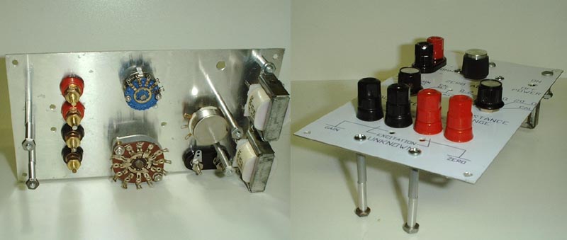
The chances are that you won't build the unit in the same sized case that I did but just in case you do here is the front panel layout.
Because of the somewhat limited resolution of figures in web browsers I have made the drawing oversized. You will have to use your own picture processing software to scale it correctly. After you get it scaled print it out on ordinary paper and stick it to the panel with double sided tape and mark the holes with a center punch and then drill. I find it easier to drill with the paper template in place. The large holes should be started with small pilot holes. I neglected to include a mounting hole for a fuse holder. You may want to include one rather than gluing the holder as I did. After you have drilled the holes, removed the paper template (in small pieces) and filed off the burs you are ready to do the label. First it would be a good idea to temporarily mount all the components to make sure everything fits. Nothing mounts in the holes marked "1 mA", "10 mA", "Gain" and "Zero". These are holes to permit access to the trimmer pots located on the board behind the panel. If you can get trimmers with screws on top, make holes for "100 mA" and "Cal Adj". Now you're ready for the panel label.
Do you remember the old days of wetting and sticking on deckles one letter at a time or using unprofessional looking Dymo tape? If you do, go and deposit your retirement check. Scale this drawing the same as you did the drilling template then print it on high quality photo paper. I used Epson glossy paper.Now you have to glue it permanently to the panel. Later on in this article I mention a kind of contact glue which is rather like an industrial strength rubber cement. DON'T USE IT. It is a light blue color and it will soak through and stain the paper. I used a "Permanent Paper Bond GLUE STICK". The color scheme of the container is green and white. The glue itself is translucent white and resembles stick deodorants. It dries clear.
Coat the paper with glue, line up the holes in the panel with the circles on the paper and stick it down without wrinkles. It might help it you have a light box. My wife is an artist and so I have access to one. Let the glue dry for several hours.
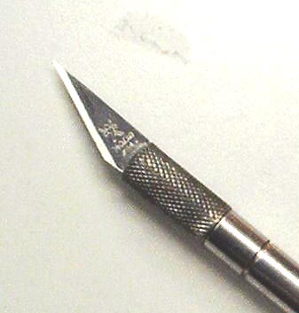
Cut out the holes and around the edges with an Exacto knife. If you have the correct blade it's not as hard as you may think. Now permanently mount all components except the circuit board. The paper is fairly rugged as paper goes but it's not as rugged as metal. Treat it with care. The binding posts do a good job of hiding the cut edges of the paper. When you tighten the nuts on the rotary switches and pot the paper may wrinkle slightly.

The knob will hide it. The off on switch is a different matter. Use two nuts on the switch, one on each side of the panel. Use a small end wrench to tighten the nut on the inside of the panel.
Solder wires on to the components which will be hard to get at after the circuit board has been mounted. Hold the board near its mounting position to be sure the wires are long enough. Remember, you want the end of the board with the bridge rectifier to be next to the transformer(s). Use the same light gage wire so as to avoid breaking copper foils away from the board. Do not twist or lace the wires together to make a harness. Moving the harness will put stress on the foils and break them away. Then mount the circuit board and solder the wires from off-board components to the board.
I started out using a 2-wire line cord and while doing the alignment I took a shock between the Low Resistance Adapter and my DMM. There was a leak in one of those cheep little transformers. I replaced the cord with a 3-wire job and after I replaced the blown op amp everything was fine.
Thank you for visiting my page at Angelfire.
Please come back and visit again!This site begun March 14, 2001
This page last updated August 18, 2001