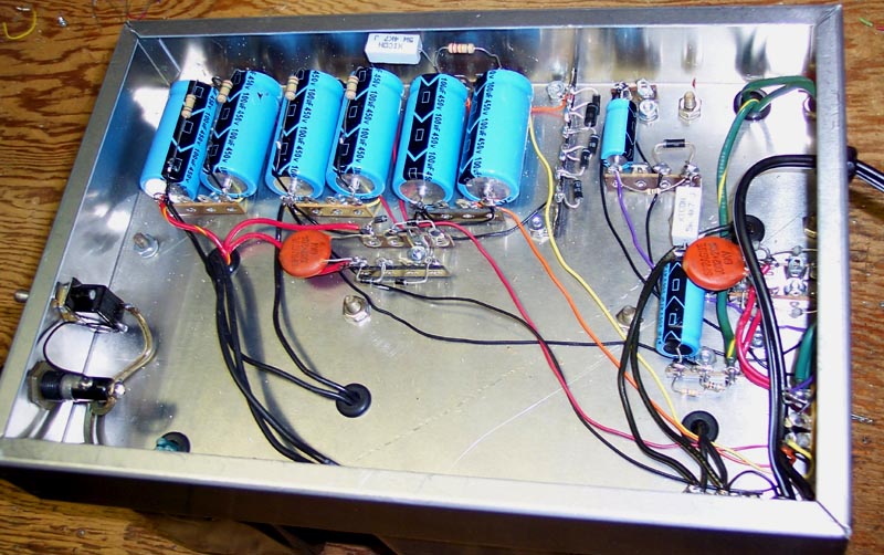
Here are the layout and drilling template. It uses a 12 by 8 by 2 inch chassis.

A verbal description of these diagrams is very difficult to do and would be quite long. If you think you could benefit from such a description, email me.
The layout is shown from the bottom, the front is to the left, and the back is to the right. The drilling template is shown from the top. The wiring color code is as follows.
These are the colors I am restricted to by my graphics program. I used different colors of hookup wire as can be seen in the photo above.
- Black -- Primary.
- Red -- B+1.
- Yellow -- B+2.
- Green -- B+3.
- Blue -- B minus and C+.
- Violet -- C minus.
The octal socket which is the power output is shown in profile as a rectangle near the lower edge and on the back of the chassis. The keyway, pins 1, and 8, are towards the top of the diagram.
Twist the two heavy green leads from the 6.3 volt transformer together and route them along the side of the chassis to the power socket. These are not shown in the diagram. Cut off the excess lead length and save it for use in the amplifier chassis. Strip about 1/4 inch of insulation and melt a small amount of solder over the leads to hold the fine strands together. Insert the end through the lower hole, closest to the socket insulation, in the octal socket lugs. DO NOT ATTEMPT TO BEND THE HEAVY WIRE AROUND THE LUG. Push the end through the hole and solder it to the lug. The solder should form a smooth curve from the wire to the surface of the lug like that seen on printed circuit boards.
Near the lower right of the drawing is a 3 lug terminal strip holding two resistors shown in blue. These are soldered to the center chassis ground lug. This is the only terminal strip that uses the chassis grounding lug. One of these resistors is the 100 k ohm that returns C+ to chassis and the other is the 10 meg ohm resistor that connects from the 6.3 volt center tap to chassis. Route the center tap wire through the maze to the lug and cut off the excess length. Treat the end as you did the other secondary leads and solder it to the lug holding the 10 meg ohm resistor. Do not bend it around the lug.
The primary connections of the 6.3 volt transformer are not shown because this part of the diagram is already rather cluttered. They run to the terminal strip which shares a mounting screw with the bias transformer. The other primary leads, switch, and fuse, wiring are shown.
Mount the line cord strain relief near the 6.3 volt transformer on the back. Mount the on/off switch and fuse holder on the front as shown. A power indicator lamp is optional.
As you have surmised from the photo above the power supply is finished and it works. It weighs in at a massive 33 pounds. That's 15 kg for the rest of the world. This weekend the power supply, next weekend the amplifier. Well...Maybe two weekends will be needed for the amplifier.
Introduction. Power Supply Schematic and Circuit Description. Amplifier Schematic and Circuit Description. Power supply chassis layout. (You are here.) Amplifier chassis layout. Initial tests and adjustments.
A foolish man dreams of wealth,
a wealthy man dreams of wisdom,
and a wise man dreams of tubes aglow all in a row.
Amplifier Smorgasbord.Or use your "Back" button to return to where you were.
This page last updated April 3, 2006.