|
Intake Manifold
Updated 4 DEC 2001
(Flange info added)
|
So you've just spent $180 on mandrel
bent 6061 tubing, from which you plan to make an
intake manifold for your CorVAIRCRAFT engine.
Sure you are skilled enough to cut
and join the pieces together, but because you don't
have a TIG welder, you are going to have to bring
the pieces to someone who does.
The real problem is how to jig it accurately, in such a way that the person doing the
welding has access to the joint to tack the pieces
together. Well, I think I've come up with an
elegant solution. At least it worked very well for
me.
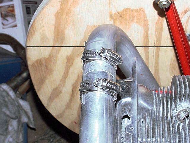
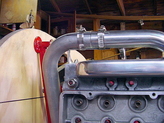
The materials you'll need are 2 hose
clamps per joint (I think it took 8 for my project) and 3
short pieced of welding rod per joint. |
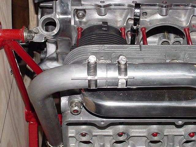
All the work was done on the actual engine for which I
was building the runners.
|
|
The intake manifold runners are made from mandrel bent
6061 aluminum
tubing, which I cut and had TIG welded for me by a local
sprint car
builder. The tubing is available from Burns Stainless
in Costa Mesa, CA
|
|
|
|
 |
|
|
|
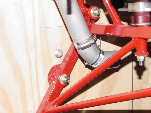
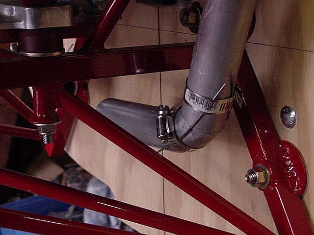
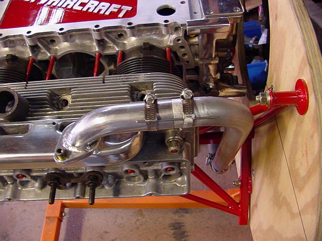
Notice in these
images, that the length of the horizontal runner (after
the bend) is not equal.
That's to compensate for the offset in the stock manifold
log's carburetor placement.
Due to these unequal length of these horizontal tubes, the completed intake runner system
is equal length, from the off centered
updraft Stromberg to each stock log.
|
|
|
|
|
|
|
But I digress...
By popular demand, I'm adding some info about milling
off the flange
and adding the new 1/4" plate flange I had TIG
welded in place.
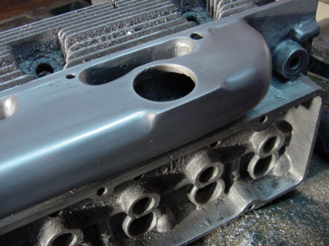
It all started with making a plywood jig in which I could place the head,
and "mill" the cast flange (carb
base) off the top of the log.
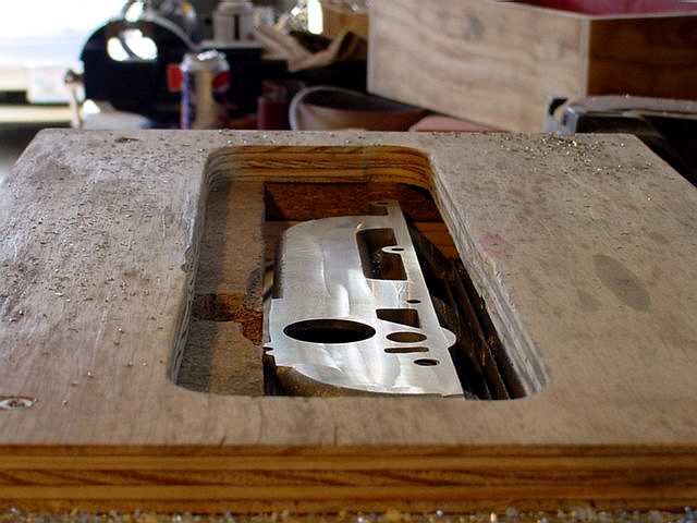
I used a 3hp wood router with a 1/2" shank,
and with carbide blades to
make short work of the soft cast aluminum.
1/16" to 3/32" cuts are quite effortless.
I use WD-40 as a lubricant and coolant.
It keeps the aluminum chips from sticking to the carbide
too
|
|
|
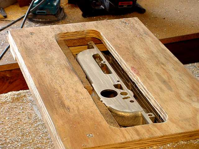
Another view of the plywood jig.
|
|
Then with my angle grinder, belt sander Dremel with sanding drum,
orbital sander, and hand sanding, I got it to
this point. From here it was
polished on a buffer wheel, using 3 different grits
of rouge.
Although I don't have photos of the next step, I
fashioned 2 matched pairs
of flanges, one pair for each head. My son
is a VW enthusiast, so there
just happened to be a stock VW carb base gasket
kicking around on my work bench,
so I used it for a template to cut the flanges to it's
exact shape.
The round hole you see in the photo above is the stock
hole that goes
through the carb base I routered off. I don't
recall the ID of the gasket I
used for a template, but my welder asked that I
make the ID of the flange
just slightly larger than the opening, to produce s "step" for him
to weld the 2 pieces together. So the ID of the
flange is about 3/16" to
1/4" larger than the stock opening.
|
|
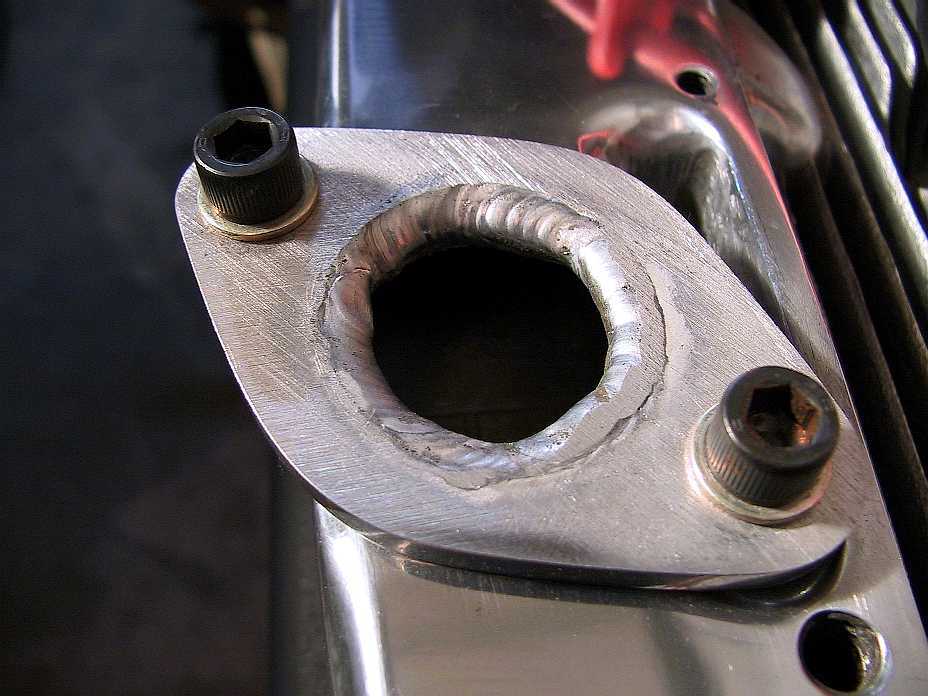
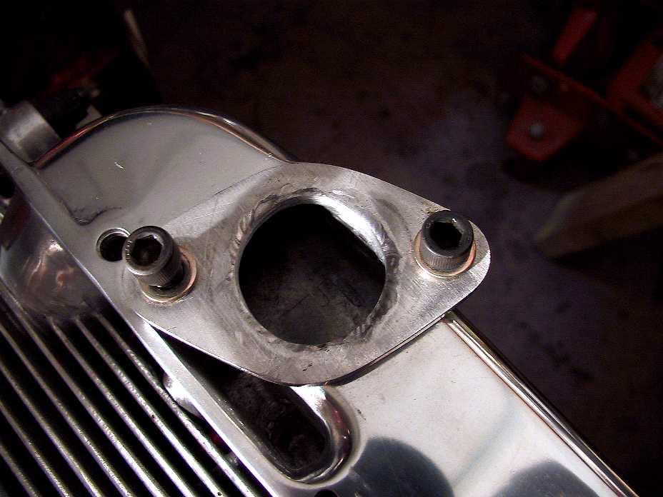
This shows the flange welded in place, with no
interior grinding. The weld
was belt sanded flush with the gasket mating
surface, but some of the weld
reduced the opening size.
Additionally, you can see that I've tapped this
1/4" piece of plate aluminum,
to receive the allen screws. These screws (with
1/4-20 threads) were tested in a
scrap piece of material, and tightened down
(with a 5" allen wrench) to a point
which almost exceeded my full strength, and
didn't strip. Don't know what
that works out to in ft-lbs, but it's stinkin'
high. I'm confident that they'll never strip
under normal circumstances, and when I'm
"done" with the engine, all allens will
be drilled, and safety wire will be installed.
|
|
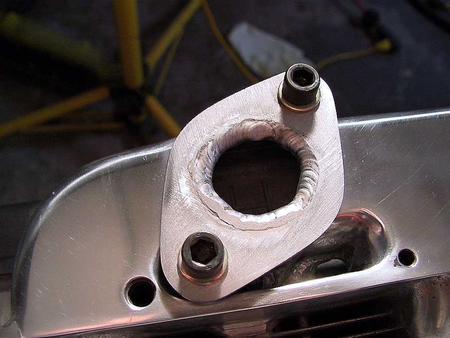
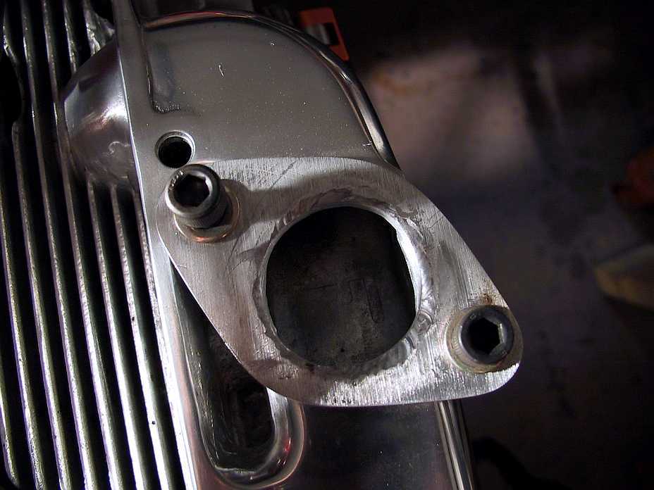
Another view... note that all polishing was done
before welding.
The welding didn't hurt the polish work, and
doing it beforehand,
ensured a nice job right up to the joint.
This photo also shows the excess material removed from
between the log and
the head, between the intake ports.
|
|
Another close up. Right clicking on these
photos, and selecting
"view image", will enlarge the photo
another 25-30%.
|
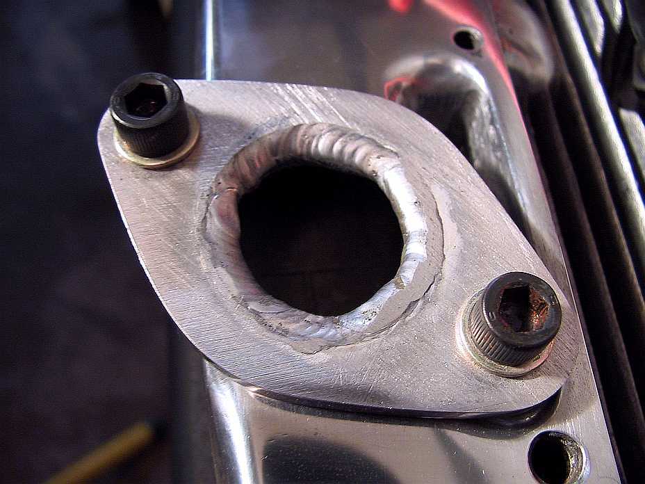
Here's a shot after all extra material has been
removed from the opening.
|
....And another view.
I may fill over the top of the weld with some JB
Weld, and grind it all
nice and square, and do the same to the mating
part, so that there's no issues
with the transition from runner to log.
|

Bottom view, showing the Stromberg
updraft mounting flange.
Notice that it's offset to one side.
This was to make both runners the same length, as
mentioned above..
|
|
|

