
Nicolas Welte and Wolfgang Moser designed this cable in 1997 as a substitute for the original X1541, according to the differing parallel port specifications of the new motherboards. With this cable you can connect a 1541 unit to the LPT port of your PC. By using programs like Star Commander, you can transfer files or full disk image files (.d64) from your PC to the 1541 and vice versa. Another interesting option is to directly connect your Commodore 64 to the PC. Using the 64HDD program, you can now manage your HD as a virtual 1541, with some restrictions.
Construction:
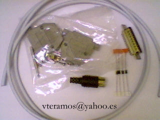
List of materials:
- One DB25 male connector with housing.
- Four 1N5819 or BAT85 diodes.
- One 6 pin DIN connector (like the serial cable of the 1541).
- 1.5 meters of six-wire cable.
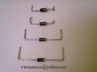
1. First, we must mechanize the diodes like in the next picture, for proper soldering:

Once mechanized, you will have something like this:
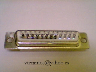
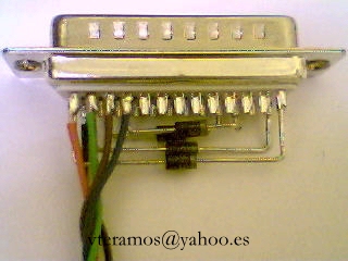
If we look at the DB25 connector, we can see little numbers on each pin. Diodes have two pins, called the anode and cathode. A cathode is identified with a mark on the diode body.
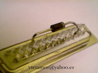
We start by wiring pins 18 through 25 together, keeping a good solder.
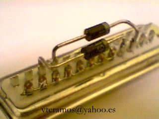
First diode: Anode to pin 10 and cathode to pin 16.
Second diode: Anode to pin 11 and cathode to pin 17:
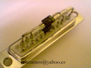
Third diode (easy). Anode to pin 12 and cathode to pin 14:
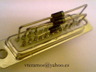
Finally, the fourth diode. Anode to pin 13 and cathode to pin 1:
A top view of the DB25 connector:
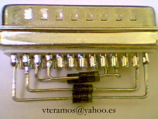
Connector wiring starts. Below, you can see the association of colors commonly used in six-wire cable with each pin of the DB25 connector. The Yellow cable is unused. If you find other colors in your cable, you can substitute them for correct concordance.
Red wire, pin 13
Green wire, pin 12
Brown wire, pin 11
Blue wire, pin 10
Black wire, pin 25 (wired together with pins 24, 23, 22, 21, 20, 19 & 18)
We will now close the housing, without damaging the wires:
Next drawing represents the DIN connector viewed from the solder side, and the colors of the cable wires.
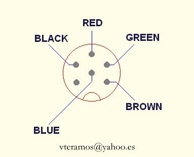
Once we have soldered the DIN connector, you must only close the DIN housing to finish.

I recommend that you test all connections and wiring before use. I'm not responsible for damage caused by using this guide. This cable works well for me.
I also recommend shutting down your C64, 1541 and PC before connecting / disconnecting any connector.

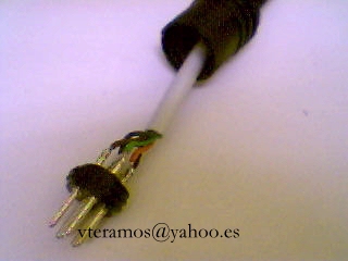
View of the Finished XE1541 Cable
You can find original schematics and more info about the XE1541 at: sta.c64.org.
Edited for English by loadstareightone. Send your comments to the author at vteramos@yahoo.es or to the editor at samicksunburst@yahoo.com .
