 or PMIs'
  ? Patent information can be inaccurate.
Mistakes
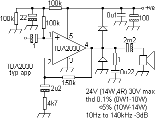
Sent: 12 May 2005. Subject: /sound4.htmlMessage: Hi, First pre-amp schematic: hmm, the BC184C has no base dc-bias connection... intentionally or just missing something? Regards, Christoph K.++++
"Reported error in circuit diagram.
Dear Christoph,
Thank you for pointing out the error in lenco.gif on sound4.html. I still have the unit and had another look at it and the error you reported has hopefully been corrected. Elsewhere, on soundb.html, I point out in respect of other designs
"The main negative smoothing capacitor for one design (on page 611) is shown reversed. Wiring as per diagram would probably result in a loud bang and not much else.
At the same time, a web-page shows a 30W FET JLH design whose speaker out is taken before the output capacitor. Such an arrangement is not good. It would probably sound crap, and cook the speaker. Another JLH design appeared in ETI (see above) with no feedback resistor, making a pretty complex, but hefty, buffer! Naturally, I am not innocent of this sin, so beware."
I've sent you a copy of the JLH diagram refered to and a copy of a light-powered mc stepup stage whose supply arrangements do not bode well for reliability.
Perhaps a competition could be contrived to award the most outrageous gaffe.
Thank you for taking the trouble and time to point out this error. After 140 days and 338 hits you were the first.
Take care, PK."
PS The output capacitor in lenco.gif is, as shown before, depicted in its' correct orientation as mounted on the PCB.
Many thanks to Bernd Rosenlecher for pointing out another error (18 May 2011).
Manufacturers' and journals' circuit diagrams can sometimes contain erroneous information. One recalls a radiograms' output stage whose heaters were shown grounded at one end and at the other. With the advent of transistors, some very strange symbols and connection details arose. When MOSFETs arrived many respected journals had difficulty in differentiating between the source and drain, let alone whether a device was an N or P-channel. The same applies to equations, eg; which is correct, Analog Devices' or PMIs' ? Patent information can be inaccurate.
Service manuals can be a particular source of humour with their cooper wire, raisin-cored soldier, fuse crips, arnaments, mulch plexers and other exotic and rare components. Others deviate in their instructions for different languages - in an English version a 1mV reading is required one minute after switch-on whilst, if you are French or German one needs 20mV after ten minutes! One respected manufacturers' diagram for a stereo amp shows clear confusion over a driver transistor, misnumbered on the PCB, that is indeterminate in that, according to the schematic and the part number in the companys' own (later) 'Survey of Semiconductors', can be either NPN or PNP. The schematic correctly shows a NPN, but a PNP is specified for that part number. Both sides of the left volume control are shown grounded. Sometimes the input polarities of opamps maybe confused. As sometimes happens, the same manufacturer in a later amplifier redesigned the entire PCB, the original case being retained. Sometimes extensive mods are required to overcome initial shortcomings. One rare and sought after tuners' circuit diagram has a very strange arrangement and assymetry in the feedback networks of the MPX decoder post amplifiers, differing wildly from the IC manufacturers' application circuit, apart from the tuner heads' local oscillator output and tuning voltage input pins having the same designation.


Care has been taken to eliminate the authors' mistakes so that others can be shown, as above, and some source material has either been scant or of a very poor quality. Deliberate 'errors' that do not affect the accuracy of the content have been included to emphasise the original and hand-rendered nature of these pages. However, no-one reported the very real problem that existed on one of my schematics (originally posted 24/11/04), despite attention having been deliberately drawn to it. This was then rectified 4 years later. If you find any that merit correction, even obvious cut and paste errors, then don't keep them to yourself, spread the wealth! Let me know and if you have a relevant and related link I'll post that too.
Linsley Hood 100W amplifier - corrections.Several errors and omissions made the circuit diagrams of the amplifier - given on p.28 of the August issue - misleading. We apologise for them and give the corrections below.
Ordinary small-signal transistors (high-voltage where necessary) are suitable for the early stages, and it was not intended to tie them down too specifically, but the types used in the prototype are: Tr1 - BC447; Tr5 & 6 - MPSA93; Tr4 & 7 - MPSA43; Tr13 - BC212; Tr10 - BC182; Tr11 - 2SK134; Tr12 - 2SJ49. The output transistors should be n-channel (Tr11) and p-channel (Tr12).
The negative supply to Tr3 should be negative, the Zener and C3 being shown upside down. Capacitors C9 and C10 can be reduced to 100uF.
Resistor values in Fig.25 are not shown, since they are the same as those in Fig.24: R5 & 8 are 1M5, R6 & 7 are 3M9 and R1 & 4 are 2M2. Care should be taken to connect the pins of Tr3 to the correct pads on the p.c.b., since the case outline is shown 'twisted' from the correct position.
WW, Sept '82, p.63
