The author used two of these in conjunction with a Comberton 12-2 mixer, an AH balanced line 8-4 stage mixer (very similar cabinet design) with a variety of tape decks (Akai 4000, Sony TC-377/399/630, Tandberg 3400X, TEAC 3340, Revox A77, Akai GXC 46D, Beocord 5000, etc) and speakers (KEF, BW, custom). A Saturn transcriptor with a SME 3012 would have suited this amp.
The P60 was the culmination of the many lessons learned on the P50 and still available until the early '80s at a cost of about �289 with the matching T55 tuner at �169, both being rather expensive for the time. These designs have proved to be quite reliable compared to earlier attempts, the (retrograde?) use of the DIN input convention and the loud switch-on transient through the speakers being the predominant short-comings. The latter could be overcome by using a soft-start which could be fitted inside the unit.
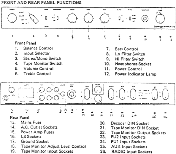
An unconventional but high quality build, some considered the placement of volume, balance and mono controls before the tape outputs as inconvenient. However, the facility for up to three tape decks to be used, the tape 2 output following the lo-filter and tone controls, could be useful.

The main preamp differences between these and the P50 include additional volume control and signal/peak indicators but no decoder, mains and phono sockets then reducing flexibility considerably which was the P50s' strong point. Specifications for this model are given as

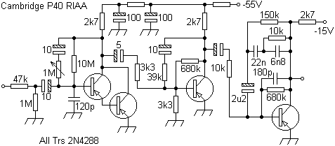
The RIAA was unconventional given the number of separate stages involved, before the final volume control. Nevertheless, similarities with the P40s' are obvious. A feedback pair has unity gain at DC and an AC gain of 6.5. A separate wafer on the input selector shorted unselected inputs to ground to reduce crosstalk. RIAA correction is given by a later stage which gives unity gain for other inputs.

In a later version (PCB iss 3) the 120pF ceramics across the 2N4401 (b-e) and BCY71 (equaliser b-c) are omitted as was the screenprinted component ident.
Care was taken to ensure that prior to any switching, a resistor grounded the decoupling capacitors so that no DC shift, due to leakage, produced transients. The preamp volume control used linear controls to achieve a 'log' law because these were more easily matched. In the centre position gain was 20dB from maximum. A drawback of this type of system is that with an intermittent wiper the output spikes rapidly.

The mono switch could have used one switch contact between two associated resistors in series with each channel. The balance amplifier gave gains of between 1.3 and 12.5 times. This was followed by an LED overload indicator (green -20dB, red clipping) and the cassette and tape 1 outputs which were loaded with a 4k7 resistor to prevent overloads.

The filters and tone controls came next. The high pass filter gave about -6dB @ 60Hz and the tone controls ±15dB at 40Hz and 20kHz respectively. The low pass filter gave a notch centred on 27kHz, roll-off starting at about 3kHz and peaking again outside the audio band at about 70kHz. The Q was switched to provide different slopes, 'steep' giving -17dB and 'gradual' giving -7.5dB at 20kHz. The tape 2 monitor and power amplifier volume control followed these.

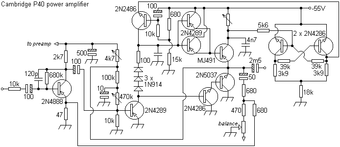
In the power amplifier, similar to that used in the P50 mk II and later models, a differential pair drove an emitter follower fed by a constant current source which reduces the current swing on the voltage amplifier. This improves cross-over distortion (particularly at high frequencies) compared to the more common boot-strapped resistor arrangement which cannot act as a constant current sink at the crossover points.
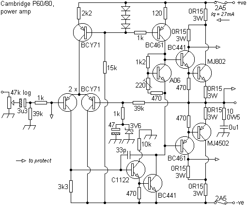
The output devices were particularly robust being chosen for their large chip and die mounting area (200W, 90V, 30A, 2MHz), and were run from ±39V rails. The same devices were used in the later Lecson AP3 and ETI System A. Note the use of a zener to clamp the feedbacks' AC decoupling cap in the event of gross output shorts to the supply rails.
The over V/I protection was noteworthy in that a FET was used to reduce the input V in proportion to the output current in contrast with other models.

This protection only turns on at the equivalent of 50W into a 2 ohm load and when it does it only adds a moderate distortion (0.2% typically) as distinct from clipping (V limit = 75V, I limit = 5A). The small capacitor prevents protection 'spikes' from appearing on the output and a LED drive circuit is triggered. Rated, by the author, to be one of the most succinct and successful systems seen.
Neil Williams has kindly shared the experience of restoring a P60 which I've taken the liberty of adding below.
"Paul,
Well, here goes. I've attached some photos of my P60. It's pretty obvious what they all
are so I won't add any explanations.
As to "how I fixed my P60" here are the details.
After using the pre-amp section to copy some vinyl records to CD, I noticed that the
volume was way down one one channel. Using the various inputs and outputs to feed
signals from a CD player into the amplifier I determined that:
1. Both power amps appeared fine
2. Channel A was quieter than channel B between the tape 1 input and the tape 2
output. This means a problem in channel A in the tone control section.
3. Channel B was quieter between the cassette input and the tape 1 output.
This means a problem in the volume, balance or equalization stages.
I only had a clunky old AVO meter which has minimum ranges of 2.5V AC and DC so
it's hard to trace audio signals. I was able to compare DC voltages on all the transistors
between the two channels and they were basically the same. I also checked the impedance
of all the transistor connections as described in page 15 of the service manual and found
nothing abnormal there.
Without an oscilloscope, I had to come up with a way of tracing audio signals. The P60 is
a great tool for this as the tape 2 input splits the amplifier into two halves. I used a normal
phono lead plugged into the tape 2 input with a short length of wire taped to the centre of
one of the input plugs and a speaker plugged into the output of that channel. I didn't have
a signal generator either (I do now - I downloaded an app for my iPad which works fine)
so I used a CD player plugged into the cassette input. This method does affect the DC
levels in the amplifier as it places the volume control (47K) between the test point and
0V. Use of an electrolytic capacitor on the test lead stops this, but I didn't see any problems
without it.
By touching the lead on various points in the circuit and comparing the signal level between
channels, I was able to determine that C13 was bad on channel B.
The other fault was a little harder to track down. Following signals in the tone control section
(which necessitated removal of the front bezel to get at the potentiometer connections on
the circuit board) showed one channel consistently quieter than the other. I could not find a
fault in this channel and eventually realised that the fault was in the channel with the louder
signals! This brought me to the conclusion that it was probably C22 at fault since in normal
operation the path through Q6 would attenuate the signal in the tone control circuit. Checking
C22 showed that it was open circuit.
I replaced these two capacitors and the amplifier worked fine. I have since replaced all the
electrolytic capacitors in the pre-amp and LED operation circuits (I found that C36 was
faulty, too, as one of the leads was rotted away!).
I also replaced R101 in the power LED circuit as the original component was burned and
the LED only glowed very dimly. I looked for a 1W resistor but could not find one so I
used the 1/2W value that was originally there. This component in under rated and should
really be 1W.
I now have a digital voltmeter which would have helped the testing enormously along with
the iPad signal generator app.
Deciding to replace all the electrolytic capacitors as the first step would have been a good
move, too! Hindsight is always 20 - 20!
I hope this is useful. Feel free to edit the above as much as you want. The photos are now
yours to publish.
Best regards and thanks again for the very helpful P60 service manual.
By the way: there is a P60 circuit diagram floating around on the web which incorrectly
shows C44 across R1. It is really across R3 as your information and the service manual show.
Cheers,
Neil Williams."
No problem, Neil. Any time. An excellent demonstration of deductive logic with limited resource. It's often an idea to consider replacing all the electrolytics in the signal paths of an amplifier of this age since these are the likeliest components to fail first and it makes life easier doing this in one go rather than repeatedly disassembling the unit. Then specifying a high temperature, high frequency type will increase longevity and (theoretically) improve performance too. The original PSU electrolytics (4,700µF, 63V) can be replaced with superior values but a soft-start (as mentioned above) should be included. The heat generated across the tarnished contacts of the mains switch on one volume control caused it to incinerate quite spectacularly. Thought also could be given to replacing the quiescent current carbon skeleton pots with sealed, multi-turn cermet types.


The distinctive input selector knob was supplemented by the unique indicators on the preamp level. The colour scheme changed from polished aluminium and black lettering. In a later version (PCB iss 3) the polished finish was retained.

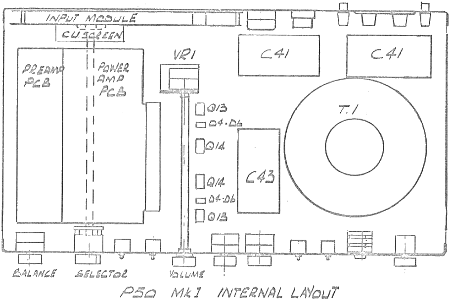
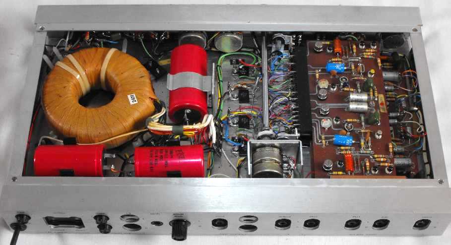
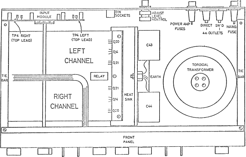
The PCBs' 'upside-down' position was determined by there being no room on the rear panel for the input sockets this been taken up almost entirely by the heat-sinking for the output pairs (now very sensibly radiating outside the unit). It is arguable that internal air-flow around the components would be reduced, but this was essentially limited anyway.

Output stages using devices with a relatively low fT of 2MHz like these might cope with lengthy wiring runs (PA PCB track layout 90° wrt to heat-sinks) but, as in the System A, these arrangements can give rise to instabilities which could, or should, have been designed out. Note also how the PA input leads (white) snake around the board and are then held in place by unrelated components. The signal path should flow topographically from input to output.

This arrangement with the input sockets directly mounted on the PCB rather than the chassis, whilst reducing wiring, could prove problematic with the plastic sockets prone to breakage if care was not taken fitting connectors. From an aesthetic point of view these further disappointed since identical sockets could be found on far cheaper Thorn (eg; Bush, Ferguson, etc) products and, frankly for the price, one expected better. A similar arrangement was used in the complex Beomaster 6000 making access more awkward, the (hefty) unit then having to be lifted when change was required. I recall one unhappy customer whose precious wooden top had been deeply scratched by the metalwork when doing this.

The switch to DIN connectors discouraged a number of potential buyers like the author who, for good reason like previous Cambridge Audio designs, had already adopted the RCA phono convention and then Technics gear.
Notwithstanding this types' fall from 'serious' use, of domestic gear of this vintage I am torn between this amp and the Armstrong 600 series (PA) particularly because of the latters' tuner (623/6, designed by Ted Rule) for which I built a number of AM loop antennae specifically for Luxembourg (208m) and pirates. Note how the P110 also emulated the 600s' styling "with a cut-away black base. The effect was to make the box seem thinner and smaller and seem as if it was floating above the table". In this model the P50 front panel layout was retained.
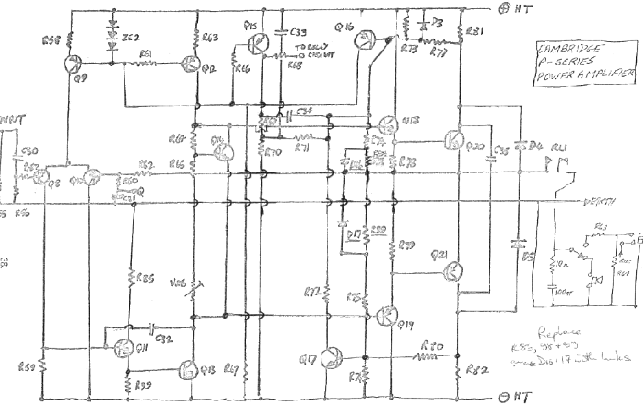
The later protection and muting circuit is shown below. Note the incorrect connections with regards mains E and the negative rail.

Contact me at paulkemble@hotmail.com
especially if you want additional content to this page
or if you find
any links that don't work. Don't forget
to add the page title or URL. Take care!
Back to index, sound, tips or home.