. tho' the culti`s back wheels stay on the ground during a turn,
both the rider and the front wheel lean into curve;
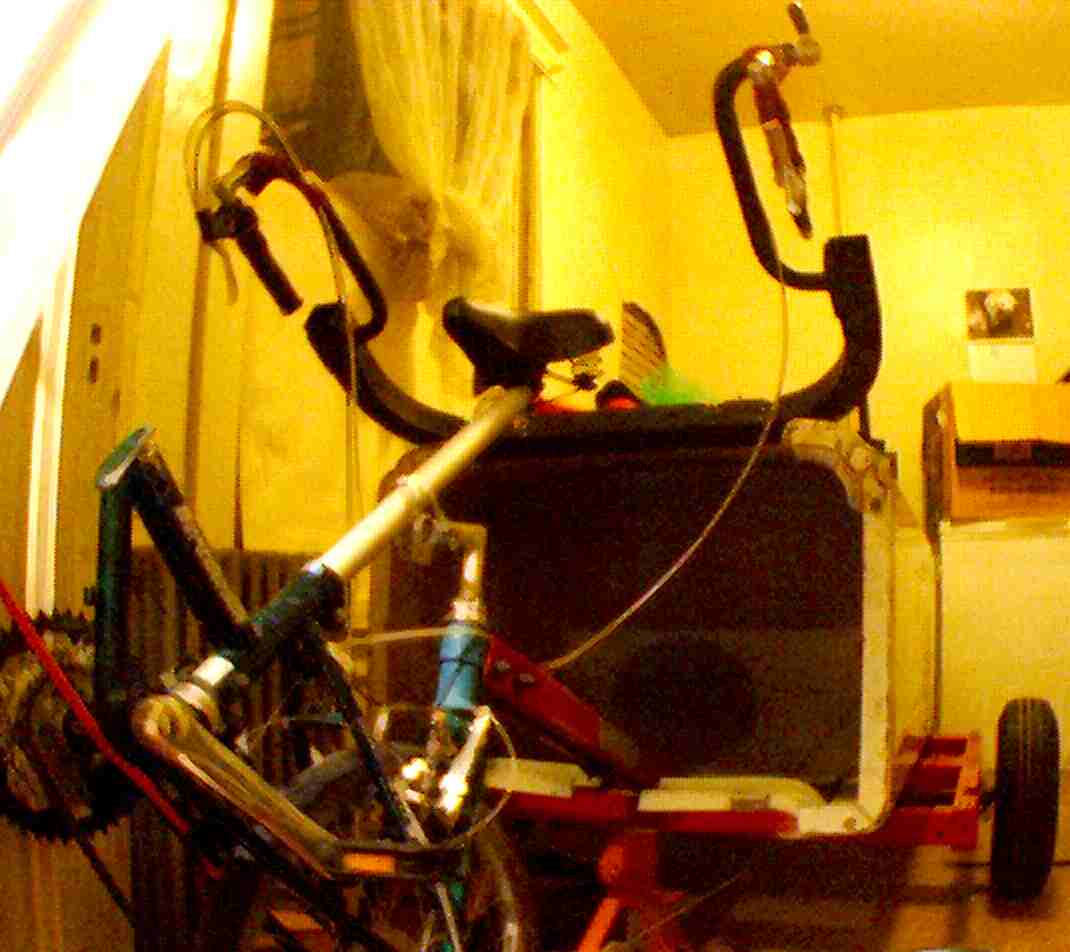
. in order to simulate that with the bike&dolly,
the rack needs handlebars, and seat needs to pivot for rider`lean .
)
6.11.5: bike.connect#
culti
6.10.30
. finding ways that the gym`parts can work:
from the gym pivot the rear bench leg provides a 45degree-angle,
and then a good connection for a 4x4 beam;
meanwhile, the gym`bench`s 45-degree angle
may help firmly bolt it to the dahon
. however,
since this morning, I've gotten a new interest
in a variation of the
bike`steering`pivot design:
. the dahon is tilted back, as in the culti design,
but then riding on the seat tube,
and u-bolted to the dahon`toptube,
is the forks of the tourbike
. I still haven't seen a safe way to connect the trailer boom
to the tourbike`steering`pivot-toptube frame .
6.11.5:
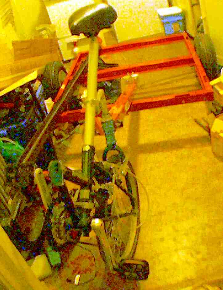
. rotate the bike backward on it`s back wheel until the seat`tube is
pointing at the trailer frame;
replace the seat`post with a giant bolt,
and insert the bolt into a set of bearings strapped to the
trailer`front`crossbeam
just as an axle`spindle gets fitted to a wheel`hub .
(7.5.8:
. this arrangment is acceptably strong only if
braking and acceleration are done by the rear wheels,
and there are no pot.holes (good luck) .

 . the plan for a trailer trike is
nearly crystalized;
. the plan for a trailer trike is
nearly crystalized;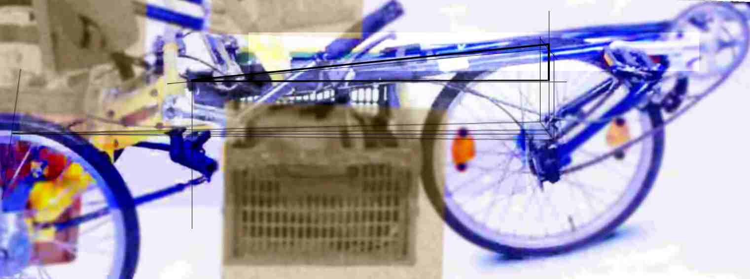


 glossary
. dahon`head == dahon`steering`bearing asm (left)
glossary
. dahon`head == dahon`steering`bearing asm (left) . is it possible to
have the current design
. is it possible to
have the current design