Site hosted by Angelfire.com: Build your free website today!

Part & Housing

Fabrication


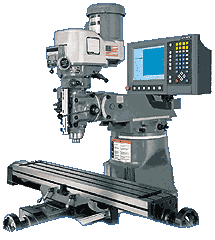
Using a YCI-Supermax 5,400RPM mill computer controlled by ACU-RITE.  MILLPWR has the ability to run G-code files from CAD/CAM programs for Full 3-D Contouring with 3-axes control/3axes readout.  With MILLPWR we can also translate DXF files directly into program code for our milling operation.

MILLPWR will enable us to:  

  • Set up jobs faster
  • Perform plastic and metal milling
  • Create, and then save, part programs
  • Prevent math errors
  • Minimize scrap
  • Improve each part's accuracy and repeatability


Hardware Features

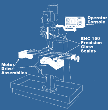
MILLPWR is a complete, 3-axes control/3-axes readout system with advanced hardware features:
 sysoverview2

OPERATOR CONSOLE
  • Easy-to-use, menu-prompted, conversational format
  • 3-D, color keypad
  • 10" flat panel, color LCD display
  • Large internal part program storage capacity
  • RS-232 port
  • 3 ½" floppy disk drive
  • Emergency stop button
  • Remote stop/go switch

POSITIONING

  • Closed loop feedback using ACU-RITE Precision Glass Scales (2µm/.0001" resolution)
  • Powerful DC servo motors
  • Precision ground & hardened ball screws


 mpconsolenew


Software Features
Keypad Layout

Main Function Keys

ABS button Switch from absolute to incremental (or vice versa) in the DRO display and milling function numeric fields.
VIEW button Manipulate your part graphic.
DRO button Display the digital readout
PGM button Display the program screen.
CANCEL button Exit from a milling function.
USE button Add a step to your program once you've completed an entry form.


Special Function Keys

INFO button MM button SETUP button CALC button
INFO button Access information about any MILLPWR function.
MM button Switch from inches to millimeters or vice versa.
SETUP button Add to your tool library, change your display options and define other system parameters.
CALC button Perform standard (+, -, x, ÷), trigonometry, geometry and RPM calculations.


Milling Functions

TOOL button RECT button CIRCLE button HOLES button
 POS buttonLINE button ARC button BLEND button

Use these keys to create a program.  All but BLEND may also be used as one-time milling functions from the DRO display.

Numeric Keypad and Calculator 

Enter program data and perform math calculations.  Press the CLEAR key to delete information from a data field.  Press the ENTER key to accept the information you've entered.

Keypad 

Cursor and Motion Control

FEED POSITIVE button
FEED NEGATIVE button

Increase or decrease your feed rate.

JOG keys

These keys enable you to position your table or move your cursor.

STOP button

Press this key once to
pause your program, twice
to exit.

GO button

Start your program.

Screen Layout

screen arrows
 

1  Status Bar Displays the servo motor status (ON/OFF), feed rate, current tool, scale and whether your position is being displayed in inches or millimeters.
2   Information Area Displays information about the job being performed.
  • Readout (DRO) - used as a digital readout, the display will show the current position for each axis.
  • Program (PGM) - when programming, a list of program steps (milling functions) and part-view graphics will be displayed.
  • Calculator (CALC) - the geometry calculator enables you to calculate missing information and then insert it into your program.
3   Message Line Operator prompts and messages will appear here.
4   Softkeys Variable milling functions appear here; functions are selected by pressing the softkey directly below each category.