One way to construct a radio is to use a series of tube amplifiers, each with a tuned circuit in its plate lead. Such an amplifier is called a "tuned radio frequency amplifier" (TRF amplifier) . A radio using these amplifiers would have to have several of them connected one after the other and to receive a particular station all of the tuned circuits would have to be set to the frequency of that station.I once saw in person, and got to play with, an antique radio from about 1920 or so that had 7 tuners and 6 RF amplifiers. They all had to be set to the same frequency and they all had separate knobs. Needless to say once you tuned in a station you didn't do much channel surfing. I can remember a radio my parents once owned and still used within my memory span that had two separate tuning knobs. It was possible to do two-handed surfing. Each knob controlled two variable capacitors.
Some radio designers were able to make 4 tuned circuits track and had them all driven by a single tuning knob. What I mean by "track" is that as you turned the knob all 4 tuned circuits were on the same frequency. This was not easy and the two handed radios were much less costly than the single knob ones. These were known as TRF (tuned radio frequency) receivers.
The reason the 1920 radio had 7 tuners was because the tubes of that time had very low gain and it took a lot of them to get enough gain to bring the radio signal up to a high enough level for a crystal or tube detector to recover the audio. By the 1930s it only took 3 tubes and so the number of tuned circuits was cut down to 4. One in the antenna circuit and one in the plate circuit of each tube. By the 1950s the tubes were even better but by then all radios used a circuit known as the super heterodyne which we will be building shortly. The Superhet, as it is called, came into wide use about 1935.
Because this site is called Fun with Tubes, just for fun, we are going to build a TRF with 1950s tubes. We only need two tubes and two tuned circuits. It's fairly easy to make two circuits track.
If we were building this project in a permanent chassis the proper shielding could be provided and we could use a triple ganged variable capacitor and two stages of amplification. Such a radio would have been as sensitive as any super heterodyne receiver but likely not as selective. Building it on a breadboard with everything open it was a little difficult to keep just one stage from oscillating.
When some of the output signal of an amplifier gets sent back to its input the result can be oscillation. To anyone who has ever operated a sound system the phenomenon of feedback is well known. In electronics there is good feedback and bad feedback. The correct name for the squeal of a PA system is "oscillation". In the case of RF amplifiers they become RF oscillators. As the overall gain becomes grater it takes a smaller amount of signal being fed back to the input to make oscillation happen. Signal is coupled back to the input through a combination of stray capacitance and magnetic coupling. Shielding (metallic boxes) can cut this effect way down but it never gets to zero. There is a practical upper limit to the total amount of gain a series of amplifier stages can have.Construction
The only way to build this circuit is to wind your own coils. If you want to try to buy coils or remove them from an existing radio you will have to ask Tube Man if you run into problems.
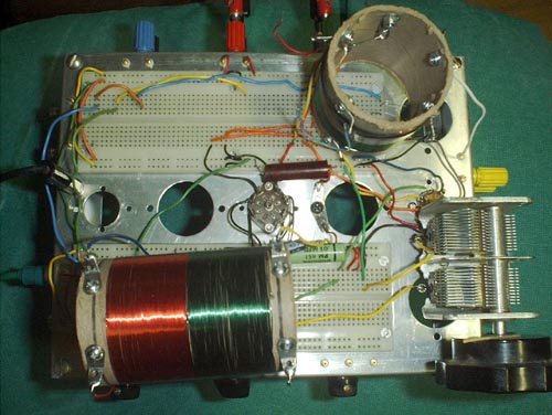
When you build the circuit you will need to take a few special precautions or you will learn first hand about oscillating amplifiers. I am going to assume that you have constructed the Practical Breadboard for Vacuum Tube Circuits exactly as I have suggested. Cut two 1 - 1/2 inch lengths of the solid hookup wire you are using with the breadboard. Solder a number 6 solder lug to one end of each wire. Mount both of these lugs with a single 6 - 32 screw and nut at the small hole next to the cutout for an octal tube socket between the two breadboarding sockets near the right end of the sockets as shown in the photo.
Use these grounding wires to ground the buses of the sockets closest to the edge. Connect B+ to the second set of busses just inside the ones you have grounded. Remember that the busses don't cross the mounting holes at the center of the sockets and you will have to use short jumper wires to connect them as shown in the picture. Mount 7 pin sockets, with wire leads attached, in the right and center cutouts for 7 and 9 pin sockets. The 6BA6 goes in the right socket and the 6AU6 goes in the left one (center hole). Place two .01 microfarad 200 volt or higher capacitors between the ground and B+ busses at the edge of the breadboarding sockets as shown. The circuit is shown below.