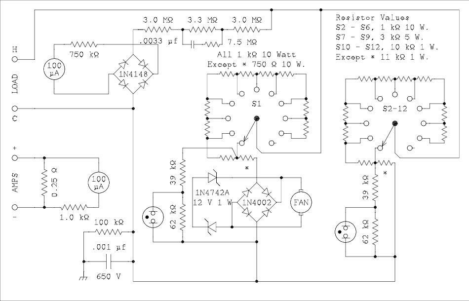

For a verbal description click here.The maximum current in each of the first six resistor chains, S1 through S6 is 100 milliamps. S1, upper left on the panel, is where the fan gets its power. At 100 mA the voltage drop across a 1 k ohm resistor is 100 volts. The fan needs 24 volts at 90 mA. The lowest resistor in the string is lowered to 750 ohms to drop 75 volts at 100 mA. The fan motor is placed in series with the 750 ohm resistor to make up the rest of the 100 volts. Two 12 volt zener diodes soak up the extra current keeping the motor voltage from going above 24 volts. The motor and zener diodes are placed inside of a diode bridge so the fan will turn in the right direction, and the zeners will regulate, regardless of the polarity of the applied voltage. The fan is only needed when many of the resistor chains are being used and there is a lot of heat to be removed from the box. If the current is small, say 50 mA The fan really isn't needed.
The voltmeter reads 1000 volts full scale. The meter circuit contains a diode bridge so it will always read up scale. The resistor in series with the 100 micro amp meter, inside the bridge, allows the diodes to work at 75 volts so the silicon diodes specified should not significantly effect the linearity of the meter. The series RC combination across the 3.3 meg ohm resistor is to compensate for AC. The meter will read the correct RMS voltage if AC is applied to the box.
The neon lamps used as overload indicators operate by the fact that the gas ionizes at a fixed voltage. The resistive voltage divider keeps the gas In the lamp from ionizing until the voltage across the bottom resistor in each chain exceeds 100 volts. This is the voltage at which the wattage rating of the resistors is exceeded.
Note: The 3 k ohm 5 watt resistors actually exceed their rating at 122 volts. The values of resistors in the overload lamp circuits have not been changed in order to maintain uniform behavior among all switches.The chain of 10 k ohm resistors has an 11 k ohm resistor at the bottom. This is because the 101 k ohms of the voltage divider on the neon lamp has a significant effect on the parallel combination resistance. Neither of my two favorite suppliers stocks 11 k ohm resistors in 1 watt power rating. Rather than go to another supplier and have to cope with a 25 dollar minimum order I decided to make this by using a 10 k 1 watt and a 1 k quarter watt in series.Neither side of the load circuit is connected directly to the chassis. Instead the common side of the load and the chassis are connected together by the parallel combination of a 100 k ohm resistor and a .001 microfarad capacitor. If you should happen to connect the load up backwards you will get a reminding tingle instead of a lethal shock. The diode bridges in the fan and voltmeter have been provided so you can test a positive ground power supply without having the two chassis's at different potentials.
In the version of the box which I built the ammeter reads 800 mA full scale. It could not be rendered polarity insensitive without going to an op amp circuit. I did not want to have a power cord on the box or internal batteries that might leak during long periods of disuse or go bad from getting too hot. The ammeter is brought out to separate terminals and may be wired with the proper polarity for the test conditions. For safety, the ammeter should always be connected in the common side of the leads from the power supply. See the operation section for connection diagrams.
The value of the 1 k ohm resistor in the ammeter circuit may have to be changed to match the resistance of the 100 microamp meter you have. Connect the ammeter in series with a DMM set to measure current and in series with a 20 ohm resistor and low voltage power supply. Change the value of the 1 k ohm resistor until the meter reads right.
If you want to include an AC/DC ammeter here is a circuit that has been fully tested and works.

For a verbal description click here.
I have included values in the schematic which will allow a meter resistance of 0.1 ohms allowing a voltage drop of 0.1 volt. In my opinion this is unnecessary. As the schematic shows the frequency response when a 1.0 ohm shunt is used is wide enough to allow the meter to be used for some audio work. The lowest resistance available from the box is 141 ohms. An addition of 1 ohm is a change of only 0.71%. This is outside the detection capability of an analog meter.
The battery and its on/off switch will always be a problem. I have a laser guide accessory for my drill press that operates from a 9 volt battery. I forget to turn it off and several days later I attempt to use it only to find the battery is dead. If you can find a relay with a low current 24 volt coil, you can connect the coil in parallel with the fan motor and connect the contacts to turn off the power to the op amp circuit when the fan is not running. I don't recommend powering the op amps from stolen power in the manner of the fan.
- Introduction.
- Schematic and circuit description. (You are here.)
- Construction details.
- Parts list.
- Operation.
This page last updated Wednesday, January 17, 2018.