A common mistake made by students in beginning electronics laboratories is to test a power supply by connecting a resistance decade box or resistor substitution box across the output. The smell of burning resistors quickly alerts everyone that someone has goofed. Often in my 33 years of teaching I wished that students in electricity labs had to pay for burned out equipment the same way students in chemistry labs have to pay for broken glassware. Perhaps they would have been more careful.
The mistake was neglecting the power. If you want to test a 500 volt power supply under a load of 200 milliamps you need a resistor of 500 v / 0.2 amps = 2500 ohms. But you can't use just any 2500 ohm resistor that comes to hand, you need one that will dissipate 500 v times 0.2 amps = 100 watts. The individual resistors in resistance decade and resistor substitution boxes are usually 1 watt. A resistor faced with a 100 times overload won't waste any time giving a warning smell but will burn out immediately. It may burst into flame or even explode.
Why Test Power Supplies.
There are formulas and charts in the ARRL Radio Amateur's Handbook and other reference books that will predict the DC voltage and ripple output of power supplies but they aren't very accurate. There are computer simulations that do a little better but are still not perfect. The best way to find out what you will get from a particular combination of transformer, rectifier, and filter circuit, is to connect it all together and test under the actual load current. To do this you need a lot of power resistors.You are probably thinking expensive but it's not as costly as you might imagine. At today's prices, May 2005, the cost of construction is about $115.
What do you do with a Load Box?
- Test an unknown transformer by placing a known load on it to see how hot it gets in long term operation.
- Test the power supply part of something you are building to make sure it will deliver the output voltage and ripple you want.
- Test bench (laboratory) power supplies to make sure they meet manufacturer's specifications.
- Test a fuse blowing piece of equipment by disconnecting the circuit from the power supply and then loading it with the load box to see if the problem is in the power supply or the other part of the circuit.
Overview.
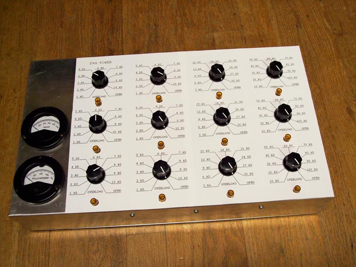
The unit built here includes analog meters for voltage and current. I realize that analog meter movements are hard to find these days so unless you have a stash of them you may want to eliminate them from the design. They are somewhat of a luxury anyway. You can always connect up a couple of DMMs to monitor volts and amps. Circuit Specialists is giving them away with a $50 minimum order.Something which you should not eliminate is the cooling fan. It's not that expensive anyway. The resistors get finger blistering hot and if you set it up with "all engines running" it can dissipate 730 watts. The fan is powered by steeling a bit of the power that is coming from the power supply. If you aren't drawing enough current to make the fan run, you don't need it.
Each of the 12 switches when set to maximum resistance will reach maximum power at 1000 volts. The voltmeter also goes up to 1000 volts but I'm not sure I will ever take mine up that far. The switches are rated at 500 volts with 1000 volts test. You MUST use the specified switches, see parts list, or something better, or you may get an arc over at 400 or 500 volts.
If you read the catalog entry you may be dismayed to see the contact rating of 125 volts. The maximum power and resistance of each resistor restricts the maximum voltage across one resistor to 100 volts in the case of the 1 k and 10 k and 122 volts for the 3 k ohm resistors. The switches are make before break so the maximum voltage you will ever switch is 122 volts. The exception to this is going from the last step to open or vice versa. You must turn off the power before making this transition. There is no reasonable way I can protect against this mistake, if you build this project, you will just have to be careful, as will I.
Figuring out overload conditions isn't as hard as you might think. There are overload indicator lights. If one of these lights comes on turn the switch to the next higher resistance or turn off the power supply. If you are at the highest setting and a light comes on you are applying more than 1000 volts and I don't recommend doing that.
The common side of the load is not connected to the chassis. Instead it is connected through the parallel combination of a 100 k ohm resistor and a .001 microfarad capacitor. The common side of the load should always be connected to the common side of the power supply you are testing. The resistor and capacitor makes it so that if you do connect it wrong you will get a reminder tingle instead of a possibly fatal shock. The voltmeter and fan motor are inside of diode bridges so you can test a positive ground power supply and still observe this precaution.
As with the headphone amplifier I have broken up this article into several pages so you won't have to wait forever for one big page to load. Here are the sections.
- Introduction. (You are here.)
- Schematic and circuit description.
- Construction details.
- Parts list.
- Operation.
Specifications.
Maximum Voltage.
1000 volts DC,
750 volts RMS AC.Maximum Current.
1 k ohm switches, 100 mA per switch.
3 k ohm switches, 40 mA per switch.
Overload lights come on at slightly over 33 mA.
10 k ohm switches, 10 mA per switch.Resistance Range.
Minimum.
137 ohms at 73 watts.Maximum.
100 k ohms at 10 watts.Maximum power.
730 watts at 1370 ohms.Overload lights.
Lights come on at approximately 10% above rated resistor power. Fan cooled resistors will operate indefinitely at this power level.Fan.
Rated at 15 CFM (cubic feet per minute). As air flow restrictions are minimal the actual flow should be very close to this value. The air in the box will be changed every 18 seconds.Fan runs at full speed with as little as 90 volts applied across the 1 k ohm resistor (90 mA) on the upper left hand switch. This is 8.1 watts. If you are operating at a lower power than this the fan is unnecessary.
Thanks goes to my wife Sue for her invaluable assistance in bringing this project to completion.
This page last updated May 22, 2005.