I wonder how many careers in electrical engineering began with the building of a crystal set. If you didn't do it or if you would like to do it again here's a way.WARNING!
Building a crystal set may lead you to a lifetime of electronics addiction. I have heard so many tails that there is no doubt that a crystal set is the gateway drug to electronics.In these modern times it's not easy to find parts. Some of you may be afraid of winding coils (it took me many years to get over helixaphobia. However my investigations have led me to the inescapable conclusion that winding coils is the best way.
That's what I thought three years ago. I have found that some of the old coil sets are still available. The P-C70-A from Antique Electronics Supply works just as well and maybe a little better than the coils you can wind. Winding coils is an interesting experiment and you may want to do it just for the fun of it. If you would rather skip all the fun you can. An additional circuit has been added below.
It's really not that hard and it is guaranteed to be painless. I have devised a method in which you use Double Stick (stickem on both sides) Scotch Tape to hold the wire in place while you wind the coil. One of the most frustrating things about winding a coil is what happens when you let go of it. The double stick tape prevents this from happening. To learn how to wind your own coils click here.
If you don't have a variable capacitor you will need to buy one. If you would rather not wind your own coils there are ferrite antennas and antenna coils for sail. Click here to learn what to buy and where to buy it.
Another source is to take a transistor radio apart to salvage the tuning capacitor and ferrite antenna. It's kind of fun tearing up one of those disgusting little things and you might learn a thing or two in the process. The parts you get are of limited usefulness which is why I really don't recommend it. If you have the time and the inclination give it a try. Just click here.
The circuit.
Here is the diagram of the crystal set.
If you wound your own coil here is how to connect it. The double dashed line is a symbol indicating that the coils are coupled magnetically. The relative position of the coils in the diagram has no relationship to the actual physical position of the coil windings. The antenna connects to the white wire and the earth ground connects to the black wire. The variable capacitor is connected to the large green winding as follows. The ground terminal of the capacitor connects to the yellow wire and the terminal to the stationary part goes to the green wire. The blue wire goes to the crystal diode and the red wire goes to circuit ground. 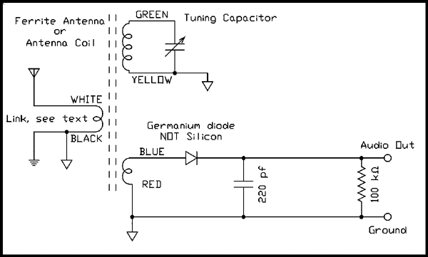
For a verbal description click here.
If you bought a ferrite rod antenna or salvaged one from a transistor radio here is how to use it. The double dashed line is a symbol for the ferrite rod. The relative position of the coils in the diagram has no relationship to the actual physical position of the coil windings. The antenna and earth ground are connected to the wire you wound around the ferrite rod antenna. The tuning capacitor from the radio is connected to the large winding of the ferrite antenna. The ground terminal of the capacitor connects to the ground end and the terminal which originally connected to the resonating winding connects there again. In other words the antenna and tuning capacitor are connected together exactly the way they were in the radio. The base winding connects to the "crystal" diode.
If you decided to buy the Hammond antenna coil from AES here is the circuit to use it in. This new circuit also includes a way to use modern stereo headphones.
The 33 pf capacitor between the primary and secondary considerably enhances the sensitivity. The capacitively coupled signal adds to the magnetically coupled signal and in addition the cap and coil form a series resonance a little below the parallel resonant frequency. This gives a considerable boost in the voltage. 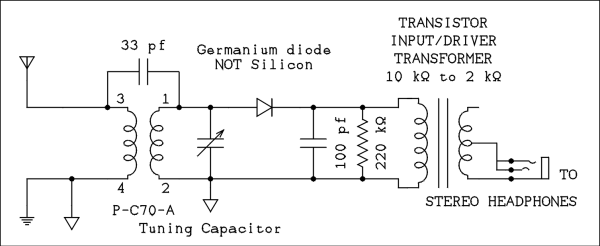
For a verbal description click here.
I have received many emails asking if modern stereo phones could be used with a crystal set. I have finally found the transformers that I had stashed away so I was able to try the experiment. The one to use is the 10 k ohm to 2 k ohm driver transformer from a transistor radio. This one is used to match the collector impedance, 10 k ohms, of the driver transistor to the bases, 2 k ohms, of the push-pull outputs. This transformer is usually red. On the side with 2 leads connect the red and green leads to the crystal detector. On the side with 3 leads the red one is the center tap. Connect the jack between the red and either the white or black leads. If your transformer has different colors the lead in the center of the three is the center tap. If in doubt make an ohmmeter measurement.
If you have a pair of high impedance headphones and would like to try them connect them between the audio out and ground of the first circuit. Or, remove the transformer from the second circuit and connect the phones there. Otherwise use the amplifier we built last or use any amplifier you have. A tube amplifier will likely perform better in this application than a transistor one.
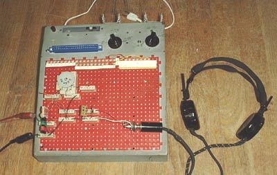
Here is how the Crystal Set looks on the breadboard with old fashioned headphones connected.
The Diode.
You will notice that the diode is specified as a germanium not a silicon diode. A silicon diode does not begin to conduct until the input voltage is about 0.3 volts or so while a germanium will conduct at about .05 volts. If you use a silicon diode the sensitivity will be poor and the sound will be distorted. To locate a germanium diode look in a semiconductor cross reference guide and start from the number 1N34A. If you happen to have an original 1N34 or 1N34A don't use it! It's an antique!From crystal and cat's whisker to a germanium diode.
When I was about ten or eleven I started experimenting with a crystal and cat's whisker handed down to me by my older brother. For those who don't know it's a little hard to describe. To my everlasting regret I don't have it anymore. I must have lost it one of the times I moved so I can't show you a picture of it. The crystal is a piece of lead sulfide mounted in a holder with a relatively flat surface exposed. the cat's whisker is a fine spring steel wire mounted so its end can be pressed against the flat surface of the crystal. The trick was to find the most sensitive spot on the crystal and the optimum spring tension.One day my friend and soul mate, Carl, came running up to my house from his which was a block away. He said "I just found out about this new thing that replaces a crystal and cat's whisker. It's called a geranium diode". Another friend, Clinton, thought it was called a German M diode. The passage of some years and exposure to the periodic table of elements got us straightened out on that one.
The Antenna and Earth Ground.
The antenna can be almost any length of wire you can string up. It doesn't have to be outside. Mine is strung from one end of my attic to the other. That's about 40 feet because the attic extends out over the car port. In general the longer the better but if you have a lot of strong local stations you may find that a shorter antenna, such as 6 feet, may actually work better.It is important to have an earth ground for the antenna to work against. If you connect a light bulb to the power line with only one wire it won't do anything. You have to connect it with two wires so the circuit will be complete. It's exactly the same for an antenna. Getting a ground used to be a big deal but not in modern homes. The electric power ground is just what the doctor ordered. Just find any piece of equipment that has the third (round) prong on its plug and use an alligator clip to make contact to its chassis. I used my bench power supply which has its DC supplies floating and a green binding post for connecting to the power ground.
When using headphones the ground is absolutely essential. You won't hear anything without it. When using the amplifier the ground may not be needed at all. I found the reception of both local stations was about the same with and without the ground. The only difference was in the amount of hum accompanying the signal. On one station there was more hum with the ground attached and on the other there was more hum without the ground. So play with it!
If your using a coil you wound you can experiment with the length of the antenna. If reception seems poor string up a longer antenna, if you are getting a large number of stations and they are overlapping so you can't listen to just one, shorten your antenna. Experiment! That's what this is all about.
If you're using a ferrite antenna you can experiment with the number of turns on the antenna winding. (That's one you wound). If reception seems poor remove the coil and wind one with more turns, if you are getting a large number of stations and they are overlapping so you can't listen to just one, take some turns off of the coil. Experiment! That's what this is all about.
How did crystal sets ever work?
A song popular in about 1950 had the theme "Remember, if you remember then honey you're much older than I." It was a duet and they were reminiscing about things from about 30 years earlier. One of the verses mentions staying up all night to listen to "Pittsburgh on a crystal set". Considering the performance of your set you may be wondering how anyone could have ever used one of these things. They don't work well today because the radio frequency environment has changed considerably since the 1920s. Major sources of interference are TV sets, computer monitors, leaking insulators on primary power distribution lines and the thousands of A M radio stations around the world.After midnight the A M broadcast band is a modern day tower of babble. It all merges together into so much noise. Between 540 kilocycles and 1600 kilocycles (inclusive) there are 107 channels. If there were only that many stations in the whole world every station would come in perfectly clear and around midnight we could hear stations literally a quarter of the way around the world.
In the 1920s there were no TV sets or computers and very few radio stations. The electric utilities used lower voltages on their primary distribution lines and the insulators were better being glass or ceramic not the inferior plastics used today.
Back then more people lived in rural areas than in cities. That meant two things; 1) they likely didn't live in an area where there was electric power available, and 2) they had longer antennas. A farmer determined to hear Pittsburgh could string up a 1/4, 1/2 or even a 1 mile long antenna or aerial as they were called. (The first officially licensed commercial broadcasting station in the united states was KDKA in Pittsburgh. It is still on the air today.) With a huge antenna and virtually no interference the owner of a crystal set could indeed pull in a station from several hundred miles away at night.
Sometimes in my fantasies I am retired to a farm in the middle of nowhere with no electricity where I don't raise anything but antennas. But then how would I power my electronics projects and how could I put them up on this web site?
HomeThank you for visiting my page at Angelfire.
Please come back and visit again!This site begun March 14, 2001
This page last updated February 26, 2004.