For a verbal description click here.
8 Simple Power Supplies.
Many viewers of this site have found the regulated power supply and amplifier is too complex for their taste. On this page you will find 8 power supplies that you can build.
Isolated (safe) power supplies.
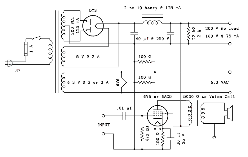
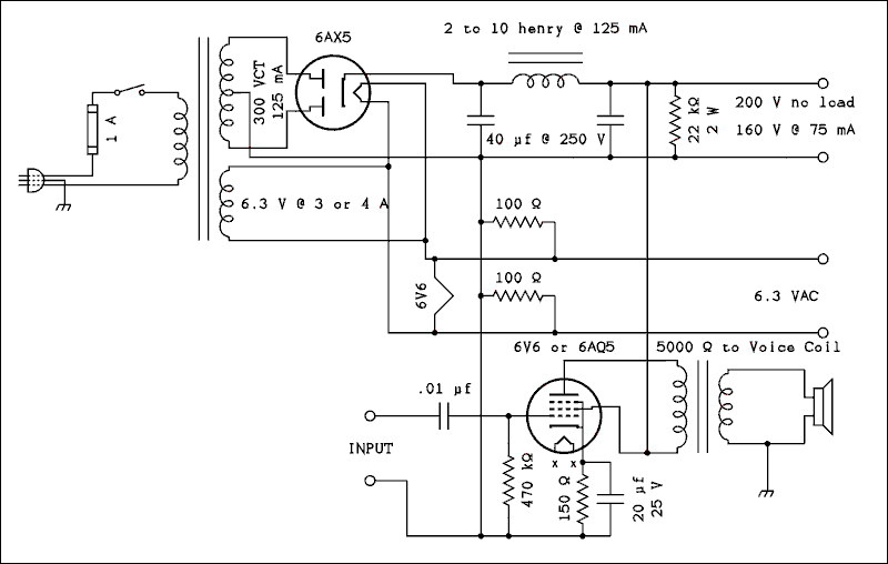
The power transformer is what isolates the output terminals from the line and makes it safe. If you can't find a particular transformer there are several alternatives among the circuits. A transformer you already have or one you can get may determine which circuit you build.The circuits that use a 5Y3 rectifier tube require a transformer with a 5 volt 2 amp winding for the tube's filament. If you can't find or don't have a transformer with a 5 volt winding one of the 6AX5 circuits may be for you.
All high voltage windings have been specified as the full voltage followed by the letters CT which stand for center tapped. Antique Electronic supply lists transformers by specifying the voltage on each side of the center tap. For example a 300 VCT transformer would be listed on the AES site as 150-0-150 at 125 mA. A 270 VCT transformer would be listed on AES as 135-0-135 volts at 125 mA.
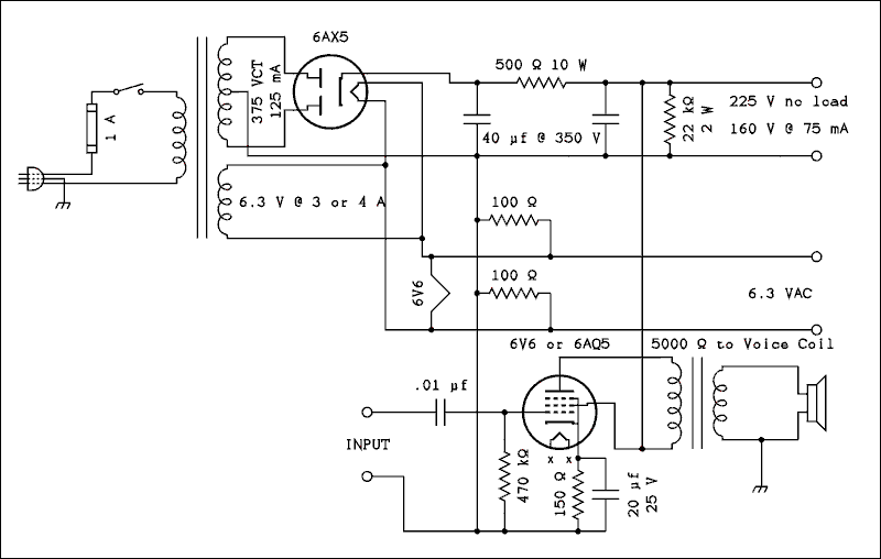
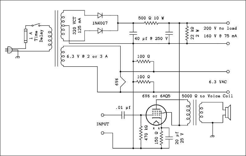
The 6.3 volt winding should have a large enough current rating to run the tubes in the supply plus those you may connect externally. The 6AQ5 draws .45 amps as does the 6V6. The 6AX5 draws 1.2 amps. The 4 tube superhet draws 1.2 amps total. A current rating of 3 amps is absolutely the minimum acceptable. I would recommend 4 amps or more.
All of the supplies have a 22 k ohm 2 watt resistor connected across the output. DO NOT OMIT THIS RESISTOR. Its purpose is to bleed off the charge on the capacitors after the power is turned off. If not for this resistor the capacitors could hold a charge for several hours. This left-over charge could be hazardous especially when used with an experimental breadboard. The resistor is called a bleeder.
We will begin with the most expensive ones to build and move to less costly. This power supply uses a filter choke and a 5Y3 tube rectifier. The audio power amplifier uses a 6V6 or 6AQ5, they are very similar in characteristics. The symbol which connects to the ground prong of the power plug means chassis ground. If you use a two prong plug be sure to connect the wide prong to the bottom lead.
All except the last one contain an audio power amplifier to complete the radio receivers described elsewhere on this site.

For a verbal description click here.
The next power supply is virtually identical to the one above except it uses a 6AX5 rectifier tube instead of a 5Y3. The 6AX5 does not require a separate filament winding. It also warms up at the same rate as other tubes which many people feel is much easier on filter capacitors.
For a verbal description click here.
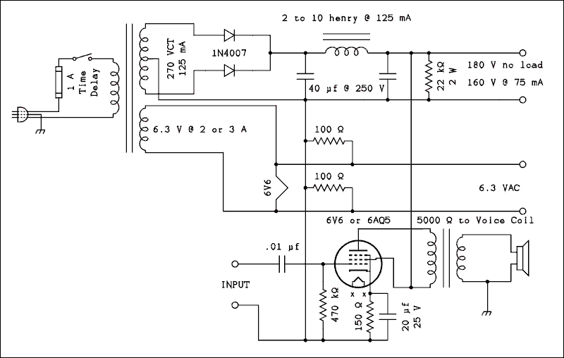
Although it is a very bad idea to install solid state rectifiers in existing equipment, a power supply which has been designed for them actually works better than one with tubes. They deliver more constant voltage output than a tube rectifier will. They also require a time delay fuse because of the high current surge at turn on. A time delay fuse is what most people call a slow blow fuse.
For a verbal description click here.
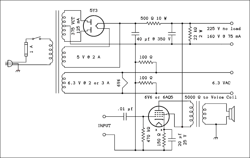
Now we dispense with the filter choke. The three power supplies above are repeated but with a 500 ohm 10 watt resistor replacing the choke.
For a verbal description click here.
For a verbal description click here.
For a verbal description click here.
Line Connected (Not So Safe) Power Supplies.
The next two are NOT isolated from the power line. That makes them dangerous if wired incorrectly. Even if the supply itself IS properly wired the electrical outlet it is plugged into may not be. Before using this supply check the outlet to be sure it is correctly wired. You should measure 120 volts between the round hole and the shorter slot. You should measure nothing between the round hole and the longer slot.I would like to discourage you as much as possible from building and using either of these last two supplies. However I must acknowledge the reality that many visitors to this site live in places where it is not easy to obtain electronic parts, especially those suitable for tubes. I offer these circuits as a concession to reality and with the hope that no one gets killed.
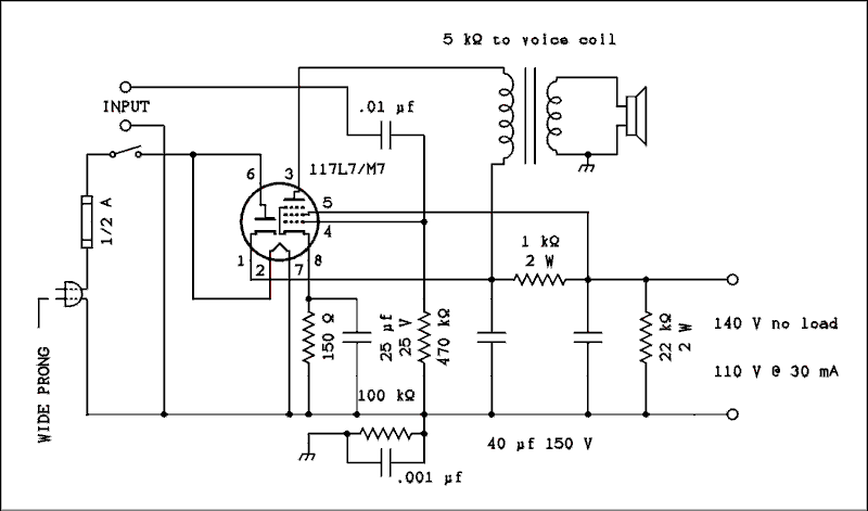
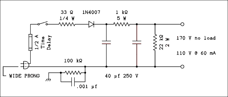
If you have trouble finding a polarized plug, buy a 6 foot polarized extension cord and cut off the outlet end. You will notice that the negative side of the supply is connected to chassis through the parallel combination of a 100 k ohm resistor and a .001 microfarad capacitor. This is to make sure the chassis gets grounded without making it a potential hazard.
This first one uses a tube that was designed for one tube phonographs. It contains a rectifier and a power amplifier in the same envelope. The heater runs directly from the power line requiring no transformer or dropping resistor. You can get this tube and the other parts you need from Antique Electronic Supply.
For a verbal description click here.
Now we are down to the bare minimum. No amplifier and just a hand full of inexpensive parts. As with the circuit above it is imperative that you use a polarized plug and that you wire it correctly.
For a verbal description click here.
This page last updated February 12, 2007.
Take me back HOME