|
Print out this page and have a
go at building a crystal radio set yourself!*
 INTRODUCTION INTRODUCTION
If you're stuck inside on a Saturday afternoon with a junk box
full of electronic parts and nothing much to do, you can spend an
hour or so and build this very simple but effective Crystal Radio
receiver. Often, the satisfaction of building these simple radios
is lost amidst the latest computer program or the latest digital
marvel chip!
THEORY
Briefly, a Crystal Radio receiver derives it energy from. the
radiated power from the AM radio stations in your area, This energy
travels in waves, and is induced into your Aerial/Earth wire system
(more about safe Aerial and Earth wires later on) and then fed into
the coil/capacitor circuit. This coil/capacitor combination is known
as a "tank" circuit, because it. stores radiated energy.
The coil stores this energy in a pulsating electro-magnetic field,
while the. variable capacitor stores energy in 'an electro-static
field between its fixed and moving sets of plates.
The Ferrite Rod acts as a bar magnet for radio waves. concentrating
them inside the turns of the coil. When.you turn the knob of the
variable capacitor you change the value of thisdevice. Changing
the value of the capacitor will vary the frequency at which"the
Crystal Radio receives. When you tune into a local AM radio station,
the tank circuit experiences what is called "resonance".
This is like a musician using a tuning fork to tune up the strings
of his instrument. Each string will 'resonate' with the chosen tuning
fork when they are both pitched at the same frequency.
!n the same way, when a radio station and the Crystal Radio are
tuned into the same frequency, resonancetakes place. This state
of resonance allows for maximum signal transfer between transmitter
and receiver. The selected frequency is then fed into the Germanium
Diode detector. This corn portent separates (rectifies) the radio
station's "carrier wave" from the program signal (voice
and music). The rectified signal is thenfed in the Crystal Earpiece
where it is converted into sound waves that we can hear.
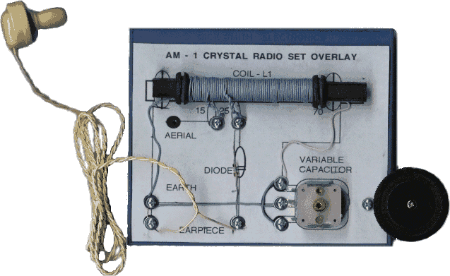
| OVERLAY
FOR CRYSTAL SET |
Parts List
Dick Smith Electronics |
| Ferrite Rod |
R5107 |
| Diode OA91 |
Z3040 |
| VC1 220pf |
R2970 |
| Earpiece |
C2765 |
| Coil wire (3m) |
W2123 |
| Aeria/Earth wire |
W2260 |
| 8 x screws |
H1634 |
| 8 x washer |
H1488 |
| 1 x b'board |
H4050 |
|
|

|
| (Refer to printable
document for accuracy) |
CONSTRUCTION
Our radio set can be made up on a square of wood or plastic
around 10cm by 12cm by 1cm. If you or a parent can solder, then
feel free to drive nickel plated nails into the wooden baseboard.
Then you can "tin" these with a bit of solder and use
each nail head as a tie point to interconnect the component leads.
BE VERY CAREFUL with soldering tools - wear
eye safety glasses at all times. Alternatively, you can use a screw/washer
combination with the DSE plastic baseboard. These should be the
#4x9mm screws and the washers around 5mm in diameter (see parts
list). If you decide to solder, take special care with soldering
the Diode and the solder tags from the Variable Capacitor. The Diode
should only be soldered by using a heat sink ( a simple device that
will draw any excess heat away from the Diode itself) and this can
be a crocodile clip attached to either end of the Diode's leadouts
(close to the glass bulb) during soldering. The caseing of the Variable
Capacitor is made of plastic, and any excessive heat applied during
soldering may well melt a part of this fragile case.
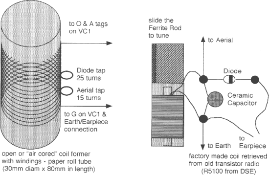
You can use other coils in this simple Crystal Radio design. You
can either wind an air-cored coil (if you can't get hold of a Ferrite
Rod easily) as shown below (comprised of the same number of turns
-70) wound on a paper roll tube complete with taps (at 15 turns
and 25 turns) or you can retrieve a factory made coil from an old,
disused transistor radio. This coil actually has two windings, and
you can tune the Crystal Radio by wiring a 120pF capacitor (instead
of the variable capacitor) across the main winding (usually 'white
and black wires) and sliding the square Ferrite Rod up and down
inside the coil former to tune in local stations (see diagram below).
AERIALS AND EARTHS
The best Aerial is one that is at least two metres high off
the ground (higher if possible) and at least ten metres long. You
MUST stay well clear of overhead power and telephone cables for
safety's sake. The safest Earth wire is one that's connected to
a cold water pipe that is embedded in moist soil. A garden tap fitting
just outside a window is ideal. Do NOT use the earth pin of a 240
volt power outlet, nor a hot water pipe, nor a gas pipe, as these
are all unsafe to use as Earth connections, and may well result
in electrical shocks or explosions occuring.
| DO NOT operate
this Crystal Radio receiver during an electrical thunderstorm. |
 |
|