
Funstuff
Box with cover removed

The big PCB on top of the left side is the cardreader PCB. There are various connectors and it looks quite messy. :)
In the middle on top of the main PCB is the modem PCB. It also carries one of the Scart-connectors.
Detail of main PCB with modem removed

To the left, with white and red labels are the original Firmware-EPROMs.
Next to them we now spot another PCB which still blocks the view on the CPU.
If we also remove this one, we can finally see the babe: Motorola MC 68341.
The CPU, isn't she pretty? :)
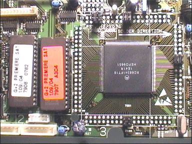
The CPU runs at 16 MHz and has a RAM of 1 MB, not much these days, I know..
BDM-connector (not fitted)
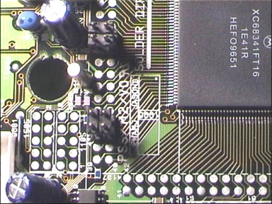
Connector 1505 (left one) is the famous BDM-connector, the same as in the Mediamaster but not fitted.
Of course you can still solder some wires to it and use it without problems. That's what I did
connected.. ready for debug..

If you wonder about the wires, back then I didn't know there was an easier way to make the FlashROMs work..
EPROMs replaced by FlashROMs
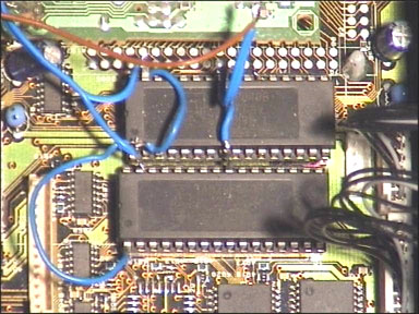
Not too complicated, or is it? ;)
I used two 29F040-FlashROMs (a 512 kByte) for this operation.
The box I experiment with all the time

Simple setup but you can have lots of fun with it, even if it's quite old. Old but cheap. ;)
November 2000
