

(These images are intended to be a bit large and do take some time to download. The way I see it if you are actually reading this then you would probably rather have larger images for better illustration.)
WHY BUILD A MULLER?
I have mixed PetroBond sand by hand and it is no fun. It is very, very difficult and I do not recommend doing such. My hands and back were sore for days but the emotional trauma may just last a lifetime. Even when mixed by hand the mix is no where nearly as good when compared to what a muller can do. Mullers are expensive for the home foundryman. Some may be fortunate enough to find a used one for a great price but others are not so lucky, like I. As a result I soon decided to make my own homemade muller.I looked for some ideas on the internet but found little at the time showing homemade mullers. The only one I found was Jerry Twadell's. After some inquiry to an email foundry list (Hobbicast) I was able to get a picture of Tom Wingo's and Cameron's muller along with some general advice from others. Other than that there was just not much available to base mine on. So hopefully this page will help if you are in need of a muller. Seeing Cameron's, Tom's and Jerry's muller along with some advice greatly helped me in building mine. In building my muller I utilized several ideas from others. So hopefully others can also utilize some of the ideas here that will perhaps expand homemade muller design. The intent of this web page was not to show how to build this exact muller but to organize and present some ideas to help someone build their own. Hopefully it will help. Since I finished my muller and put the page up there have been several other muller projects people have done that I have added as well. I have worked on this site over about 1 year so it is a bit long winded.
MULLER DESIGNS.
A muller does not have to be very complicated, but somehow my design always ends up that way. Trying hard to stick to a commercial design, I based my design on the MIFCO ML-125. Mixing the clay with the sand particle requires a mixing as well as a squeezing motion. The MIFCO unit does this by using wheels (rollers) and plows (scrapers). Most commercial units I have seen use this concept to process the sand. That is not to say this is the only way to mull sand.


There is also a mini-muller project going on in Hobbicast by Dave (Oldf47). This idea is using a 5-gallon bucket, plastic wheels, and a drill press. You can see the files of it at: http://groups.yahoo.com/group/hobbicast/files/Muller%20Project/
Dave has currently revised the muller to have a dedicated motor opposed to utilizing a drill press for the drive. The pictures below show the mini drive train that spins a bucket around a fixed carver blade. The buckets can be traded out and used for sand storage. I am really interested in where this project will end up. I think that most home foundries could get by with a small muller such as this. It would be very easy and cheap to make. You can now check it out more at Oldf47's
top secret laboratory located somewhere in Ohio. Here are a few additional comments Dave sent me about the design:The mini Muller seen here spins a bucket of sand to be mulled around a fixed carver blade. The buckets can be switched out and used for sand storage. It uses a 1/2 hp motor and a two stage belt system to spin the bucket at 120 rpm. It was designed Dave Gingery style, to be built with basic hand tools, with parts and material coming from home improvement and hardware stores. I have mulled 20-pound batches of K-bond and water tempered sand and it works well. I am with Scott on this. No mater what type or style of muller you go with the time and labor they save are well worth the time to build one. And that the sand comes out better than you can mix by hand is icing on the cake.


A plywood pulley, good idea! Check out the mulling action going on inside.
Roy the "Chipmaker" has also built an incredible muller. He has mentioned that he utilized some ideas of Cameron's and I (glad to hear the page has worked). He has at least made a lot of improvements over mine, that's for sure. Roy has really done a good job with his plows. I got really lazy on mine towards the end and built plows that lacked efficiency. They work fine but could be improved upon. I am very impressed with Roy's design and quality. He has made a fine machine. You can read more about his muller at the
Sand Muller Construction page.
LAWN ROLLER MULLER - I have not built this but it's just an idea for what I think would be the easiest and cheapest muller to make (other than your hands). It might work well for someone who only occasionally needs one. It could be built very quickly and require no motor to be rigged up. The idea is basically like a roller used for smoothing and compacting soil or pavement. The rolling bin could be pulled behind a riding lawn mower. Something perhaps made out of a 55 gallon barrel. Perhaps making two axle stubs on the ends of the barrel and hook a chain to. This could serve as the pulling points. One could place all the ingredients inside the barrel then add an old bowling ball, which will serve as the squeezer and mixer. Let me know if you try this. I'm really curious.
MY DESIGN.

With a 1740-rpm motor and knowing I needed a final speed of about 20-30 rpm, I pondered the question of gearing. I started to use some large pulleys that I took off of old farm equipment. However this proved costly by the time I mounted them on shafts with bearings and the arrangement would be bulky. In order to make it more compact and eliminate some bearings I then thought about using an old lawnmower transmission but abandoned this too because it was already worn and not easily adaptable. In the end a manufactured reduction gearbox proved easily to be the best design. Garden tiller gearboxes are a common item that would work well too. I chose a 40:1 unit manufactured by Ohio Gear. It was new and cost $49.00. The type of gearbox I used can be purchased off EBAY for great bargains. Search under "speed reducer" or "gear reducer" and typically 5-10 will come up. Don't get in a hurry and you can easily get a better deal. Nobody else even bid on the unit I purchased. With a 40:1 reduction and then with a 2.04:1 chain drive the mull rpm would be at about 21.3 rpm. That is a bit slow compared to commercial units which I think typically turn at 30-40 rpm. However this gives it more torque and I would like to ensure it had plenty of power so as not to have to change it later. The speed turned out to be about perfect for the muller I think. The motor is not loaded down much at all. It starts easily under load and runs cool. The motor does kick hard when not under load. Cameron has a soft starter on his to alleviate this problem. There is a description of such on his webpage. The gearbox does get hot after about 30 minutes of running. The horsepower rating of the gearbox is actually lower than the motor, which may explain the high temperature. However for the use in this situation I don't think it will be a problem.

The muller wheels need a bearing spindle and hub. I could have used some trailer wheel spindles and wish I would have. However, I machined my own bearing hubs from a piece of 2.75" O.D. x 1.85" I.D. pipe. If you have a lathe with enough capacity then boring holes in the wheels for the bearing would simplify things a lot. I could have bored them with my mill but don't have a boring head.

Cutting the bearing hubs on the 4"x6" bandsaw. I like this little saw a lot. I previously used a chop saw but this has completely replaced it. This is slower but not nearly as deafening. It is more precise, operates unattended, and turns itself off when finished. Well worth the $139.99 it cost.

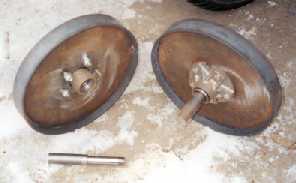
Here are the muller wheel spindles and bearings. The bearings are a set of 1" trailer wheel bearings. For $9.95 you get two 1" I.D. x 2" O.D. bearings and a seal. Much larger than needed but the price is right. I turned out the inside of the stock to 2.00" on each side to insert the bearings. The axle is a 1.25" round that I turned the end down to 1" on. The seal rides on the 1.25" section. I then cut a grove on the outer end (not shown) to secure the unit with a snap ring. The spindles works nicely but take a while to fabricate. Ready to go spindles would be a big time saver.

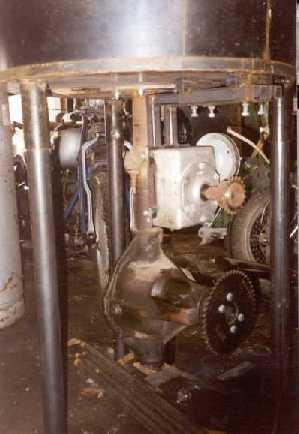
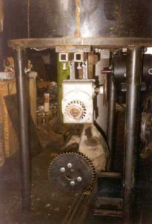
Here is the gearbox sprocket for the chain drive. It is a 25 tooth 4-speed Harley Davidson Big-Twin motorcycle sprocket. I had it on hand due to some motorcycle gearing experiments. The only problem was the bore had splines for the shaft. I turned these out and purchased a hub from a farm supply store then welded it in. Worked well.

The mainshaft sprocket is a 51 tooth Ironhead Sportster sprocket. The hub was slightly too large for the inner bore. I could not fit the sprocket in the lathe so I turned the hub down slightly then welded it in place. A friend donated the 51 tooth and I had an old chain on hand so this drive cost me only what the hubs cost. Should easily handle the load.

This is my quality control inspector. She cuts me no slack at all.

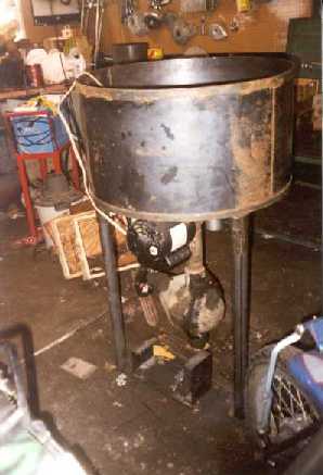
As you can tell by the wagging tail I passed the QC check and it is starting look like a muller. The protruding shaft will connect to the mull assembly. Notice how the motor extends beyond the edge of where the tub will be. At first thought I did not like this but it really simplified the design. I did see some opportunity in this extension though for a shelf where I can set my ingredients to add. The shelf will also protect the motor from sand being dropped on it. I always put my tools on wheels when possible. This was no exception. Notice the bottom front cross member is inset to allow more clearance for a tub to be placed for sand collection.

In order to keep the sand from falling out where the shaft comes in from below a collar trap is used. This complicates things some but should provide an everlasting solution with adjustment allowable. I debated against using; a seal made from some greased rope, a typical wheel bearing seal, or the collar. The wheel bearing seal would allow for practically no side adjustment so I decided against it. The rope seal was a good idea I thought since it was cheap, easy to replace, allowed for some slight adjustment, and simplified things by not needing the collar. However, I went with the raised collar instead. The pipe shown above is welded to the bottom of the plate shown. The plow brackets are then welded to the pipe. The plate has a groove machined in it to help align the pipe when welding. The 3/8" plate is bored in the center for the 1.375" shaft to penetrate through. This allows for two heavy welds on each side of the plate. Another reason it extends through is to allow a bracket to be attached for the wheels to be raised in order to disengage them or to reduce squeeze pressure.

Here you can see the door to dump the sand. It is a 3/8" plate with slots machined for the rails. The door is designed to be self-cleaning so as not to be clogged with sand. Worked great.

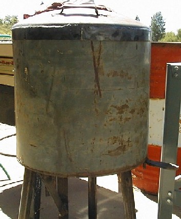
Here is the muller tub, which makes up the bottom and sides. It is about 30" in diameter. The tub is an end section of an elevated diesel fuel tank used for refueling tractors. The tank was sitting in a pasture and had several holes already rusted through. It is thinner than I would like but will do the job for now. I cut it apart with a scroll saw. It could be replaced later on with a thicker rolled section and bottom plate. The protruding pipe you see is part of the collar trap. It is a section of 2" exhaust pipe. The shaft goes through it and the thicker pipe welded to the plate comes down around it to create a trap for the sand. There is about 1/4" of adjustment that the tub can move in any lateral direction before contacting the collar assembly. Nothing I make is too precise so this play really helps in adjustment.

Ford tractor blue. I sure do like that color. Tractor and implement paint is very durable, inexpensive, and available at about any farm supply store. You just have to like the color of tractors. I buy it by the gallon, thin it with lacquer thinner, and spray it with a paint gun. Once opened try not to keep it over a few months because it doesn't store too well. However if you do, you can break the skin off the top and thin it some to extend the shelf life. It is also sold in spray cans for touch up work.

Viewed from the other side. Notice the clamps connecting the muller tub and frame. These allow for lateral adjustment of the tub to center the shaft.

Here is a view of the drive-line when finished. The chain cover keeps the sand off the chain and also is essential for protection. Get a hand caught in the chain and it will be cut off. The dumping system works great. Plenty of room to get a bucket or tub under it to catch the sand. Glad I recessed everything for the clearance. I really do like that shelf to. Comes in real handy.
This is the actual mulling assembly. The tub is only painted on the top portion above the sand line. The plow design could use some more experimentation but it works ok the way it is. The idea was that the straight plow would hopefully push the sand out and the angled plow would bring the sand in while putting the bulk of the sand in the path of the wheels in a windrow. I know, that is asking a lot of such a simple design. The plows are made from a 1/2"x2" flat. The muller can handle 100 lbs of sand well but a batch that size is too much sand for a windrow as is. I don't know what I was thinking. The angled blade piles up more sand with the bulk of it out toward the end. The straight plow piles up evenly distributed for the most part. The sand piles up in front of the plows and then falls over the back. The sand dumps quickly at first but takes a while to get the last 15 lbs. or so out. Over all it has good distribution and seems to mix and rotate the sand well. The plows are not the most efficient design but overall the mull works well so I think I will leave it as is.

You can't see them too well because of the sand but 4 bolts attach the plows. The holes are slightly oversized to allow for some adjustment.

The brackets above are to disengage the muller wheels for a final fluffing stage. There is a pin on the angled scraper support that they attach to.

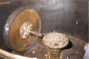
Here is one of the muller wheels. You can probably figure out what it is but just in case it is a 25lb-weightlifting plate. I drilled two holes for mounting. This iron was very hard to drill. I would suspect most iron that is used simply as weight will not be the best quality and this was no exception. I removed the paint on the wear surfaces. The bearings are sealed on this end by a cork gasket. The gasket is bolted between the hub and wheel. Keeps dirt out from the wheel opening and seals the connection of hub and wheel. I should have used some rubber like on the arms but the cork worked well.
